Programming and operating manual Model 1001 DFB
16 FICEP S.p.A.
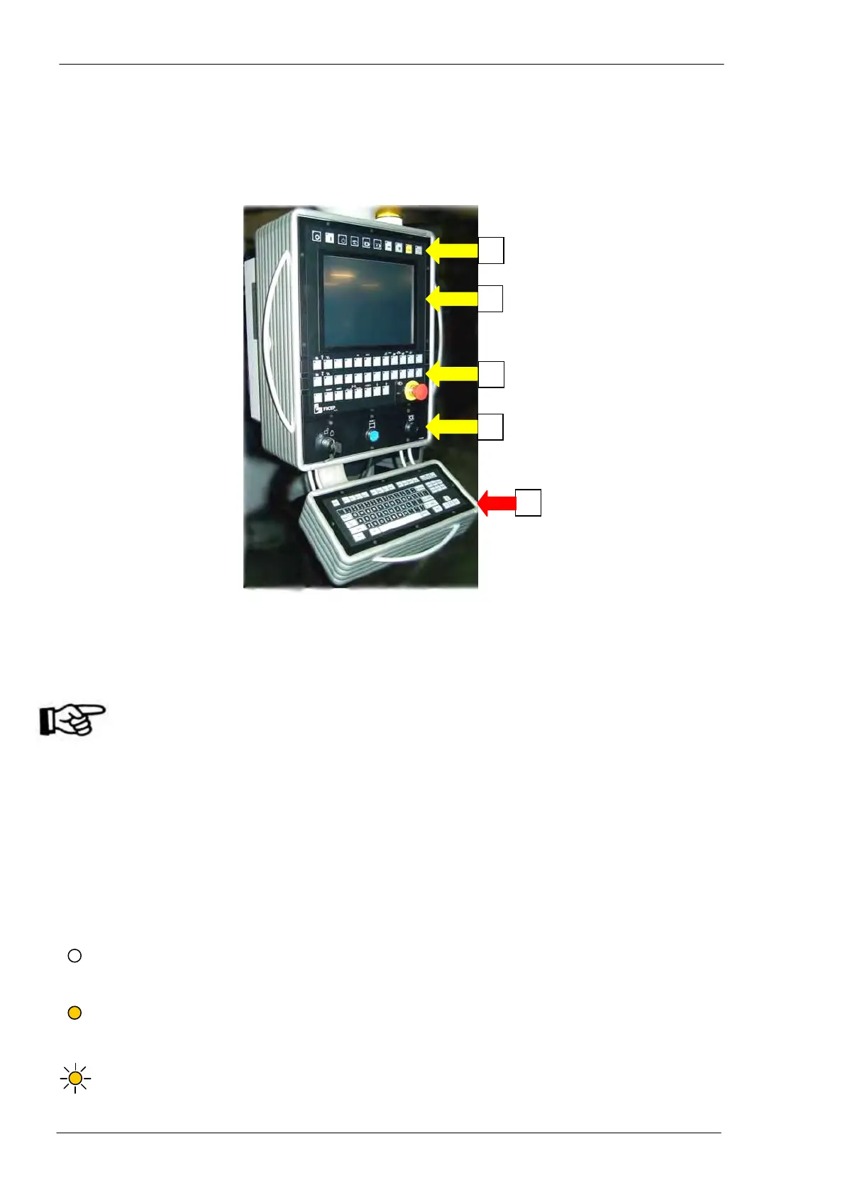
Operator’s position
The operator’s position, connected to the drilling machine, is build up from a colour video, some push-
button stations and a PC keyboard.
Through screen and keyboards, the operator can program and completely control the line.
1) Main push-button panel: push-button and selectors switches necessary for the manual or auto-
matic execution of the main operative functions.
2) Colour screen: with touch screen function
3) Auxiliary push-button panel: this includes special functions typical of each line (ex. vices,
pincher controls, etc…)
In this zone, there is an emergency push-button with mechanical reset. When activated, all
actuators on the machine and the auxiliary circuits are immediately switched OFF. To re-
store the normal functioning, it is necessary to unlock the push-button (depending on the
different model it is required to pull or to clockwise rotate the red head) and to push again
the “RESET” push-button with blue warning light sideways to the main electric switch.
Another emergency push-button is on the portable push buttons panel for maintenance
operations (see “Portable push buttons panel for service operations”, page 38).
4) Controls and protections zone: Key type selector switch to lock the machine in safety mode for
tool setup, STOP push-button for drilling cycle and protections alarm RESET push-button (acti-
vated by interruption of protection barriers round the machine, if provided).
5) Alphanumeric keyboard: standard PC keyboard having letters, numbers and others symbols; it
is used to input data and information, to edit programs, etc…
Main and auxiliary push-button panels - Push buttons with LED included may properly be considered true
two-position selector switches:
If the LED is not illuminated, the selector switch is in OFF position and the relevant command is
not activated. To move the selector switch to ON position, just press the push button and wait till
when the LED is illuminated.
If the LED is illuminated, the selector switch is in ON position and the relevant command is acti-
vated. To move the selector switch to OFF position, just press the push button and wait till when
the LED is no more illuminated.
If the LED is blinking, it signals the system availability to accept the command of the push-button.