Model 1001 DFB Programming and operating manual
FICEP S.p.A. 53
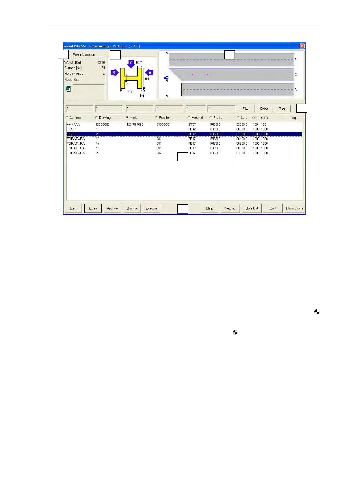
The programming window
Programming window zones
Zone 1: general information about the part program selected in the zone n. 5
Zone 2: profile type and relevant geometric measures of the part program selected in the zone n. 5
Zone 3: drawing not in scale of the part program selected in the zone n. 5
Zone 4: controls to select and put in order the part programs according to the chosen criteria
Zone 5: list of the part program stored in the CNC
Zone 6: operator controls
Remarks on the contents of the zones
Zone 2, profile: the ►│◄ symbol identifies the datum line side or the “A flange” of the profile, whereas
identifies the part origin.
Zone 3, drawing: the profile is represented “open” on the plane and the symbols determine the origin of
each side of the profile; the profile sides are identified with “A”, “B” and “C”. In the drawing, also the posi-
tion of the feeding pincher is represented in blue colour.
Zone 4, selecting controls: pressing the “Filter” push-button, a window is displayed where it is possible to
choose the selection criteria for the pieces listed in the zone n. 5. Pressing the “Order” push-button, a win-
dow is displayed where it is possible to choose the order criteria for the pieces listed in the zone n. 5 or for
the selected pieces. The chosen criterion is identified by a selection mark.
Zone 5, parts list: to select a particular part program touch directly the screen or use the arrow keys of the
PC keyboard; the selected part is identified by a blue bar.
Zone 6, operator controls: the push buttons of this zone allows operating with files and nesting programs,
in detail:
“New”: to edit a new part program
“Open”: to modify an already existing part program selected in zone n. 5
“Execute”: to generate the canonic program for the part selected in the zone n. 5 as “piece cut to
length”
“Graphic”: to display a window with a scaled graphic view of the part selected in the zone n. 5