Programming and operating manual Model 1001 DFB
104 FICEP S.p.A.
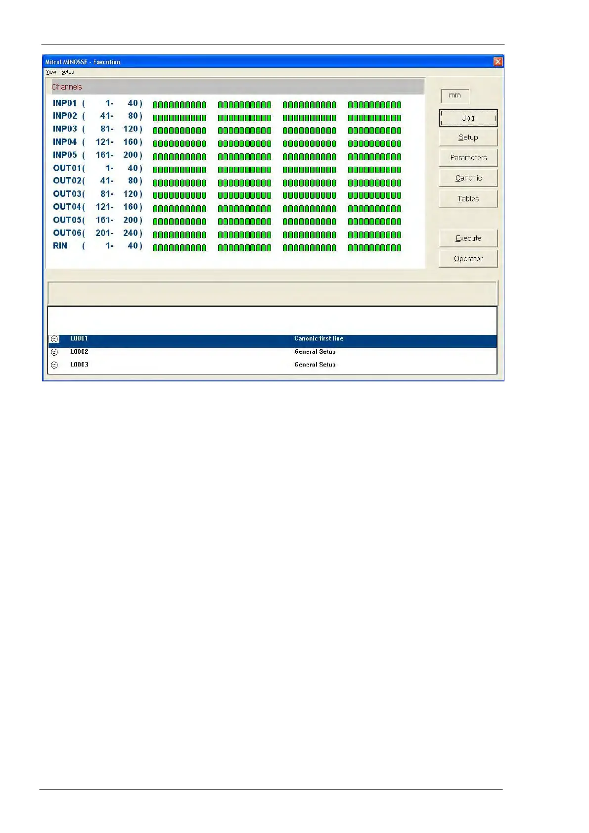
Layout and function of all push-buttons doesn’t change while a matrix of little graphic symbols takes place
of axes coordinates. Each little graphic symbol represents a single I/O channel.
The condition of following object is represented:
INP input channels (helpful for factory maintenance service)
OUT output channels (helpful for factory maintenance service)
RIN internal relays (helpful for FICEP installers and technicians)
First row of the matrix is called “INP01 (1 - 40)” and display the condition of all digital inputs “addressed”
from 1 to 40; the second one for inputs from 41 to 80 and so on.
The meaning of colour of little graphic symbols is:
- little graphic symbol green for an input channel: low level condition (F.I. normally open sensor not
energized)
- little graphic symbol red for an input channel: high level condition (F.I. normally open sensor ener-
gized)
- little graphic symbol green for an output channel: low level condition (F.I. coil of an solenoid valve
not energized)
- little graphic symbol red for an output channel: high level condition (F.I. coil of an solenoid valve
energized)