4/5
3. Mode
35210
35210
Maintenance
*1. Even though the laser unit is in normal condition, it may take five minutes or more for the Laser Synchronous Sensor to turn from
Asynchronous to Synchronous.
!
!!
! Paper Advance Section 1
*1. Printer door 4 is shown only when the Quad Magazine Unit has been registered to Option Registration.
!
!!
! Paper Advance Section 2
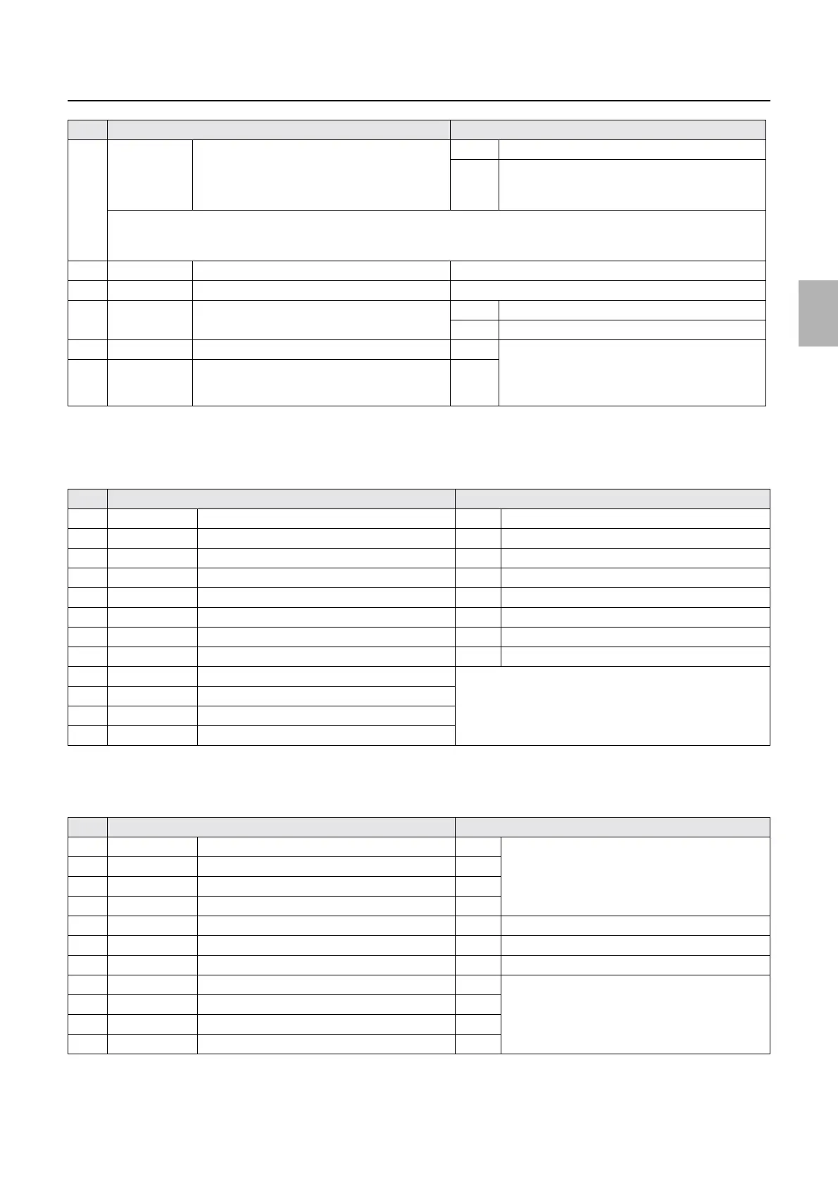
4 OK/No Good G Laser Light Source Status OK The laser and G laser driver are normal.
No
Good
The laser unit is deteriorated.
The G laser driver is not connected correctly, or is
damaged.
The laser light intensity depends on the electric current applied to the laser diode. When the laser diode is being deteriorated, add
the electric current to acquire the specified amount of output. No Good is displayed when the current value exceeds the
limitation.
5 ##.#C R Laser Thermosensor Displays the R laser temperature.
6 ##.#C Laser Unit Thermosensor Displays the temperature of the laser unit.
7 ##### Polygon Mirror Frequency 2043±7 When the polygon mirror rotates properly
- The polygon mirror does not normally rotate.
8 ON/OFF G Laser Judgment Signal 1 OFF The combination of ON/OFF identifies the laser
unit type.
For details, see
☞Exposure Engine Section
(Details).
9 ON/OFF G Laser Judgment Signal 2 OFF
No. Display Status
1 DARK/LIGHT Paper Sensor 1 DARK Paper is detected.
2 DARK/LIGHT Lane Select Sensor (Left) DARK When the arm is detected.
3 DARK/LIGHT Lane Select Sensor (Right) DARK When the arm is detected.
4 DARK/LIGHT Arm Sensor (Left) DARK When the arm is detected.
5 DARK/LIGHT Arm Sensor (Right) DARK When the arm is detected.
6 DARK/LIGHT Paper Sensor 2 (Left) DARK Paper is detected.
7 DARK/LIGHT Paper Sensor 2 (Center) DARK Paper is detected.
8 DARK/LIGHT Paper Sensor 2 (Right) DARK Paper is detected.
9 ON/OFF Interlock Switch (Printer Top Cover) See
☞Operation of the interlock switches.
10 ON/OFF Interlock Switch (Printer Doors 1, 4)
*1
11 ON/OFF Interlock Switch (Printer Door 2)
12 ON/OFF Printer Door 3 Sensor
No. Display Status
1 ON/OFF DIP Switch 3-1 OFF Displays the dip switch status of the printer control
PCB.
☞66000
Turn off all.
2 ON/OFF DIP Switch 3-2 OFF
3 ON/OFF DIP Switch 3-3 OFF
4 ON/OFF DIP Switch 3-4 OFF
6 DARK/LIGHT Pressure Guide Sensor DARK When the paper pressure is released.
7 DARK/LIGHT Paper Advance Pressure Change Sensor (Left) DARK When the pressure is applied on the paper.
8 DARK/LIGHT Paper Advance Pressure Change Sensor (Right) DARK When the pressure is applied on the paper.
9 ON/OFF DIP Switch 4-1 OFF Displays the dip switch status of the printer control
PCB. ☞66000
Turn off all.
10 ON/OFF DIP Switch 4-2 OFF
11 ON/OFF DIP Switch 4-3 OFF
12 ON/OFF DIP Switch 4-4 OFF
No. Display Status
Distributed by: minilablaser.com