D
IRECTION FR091521, REVISION 1 VIVID S60N/VIVID S70N BASIC SERVICE MANUAL
Chapter 8 - Replacement Procedures 8-161
PRELIMINARY
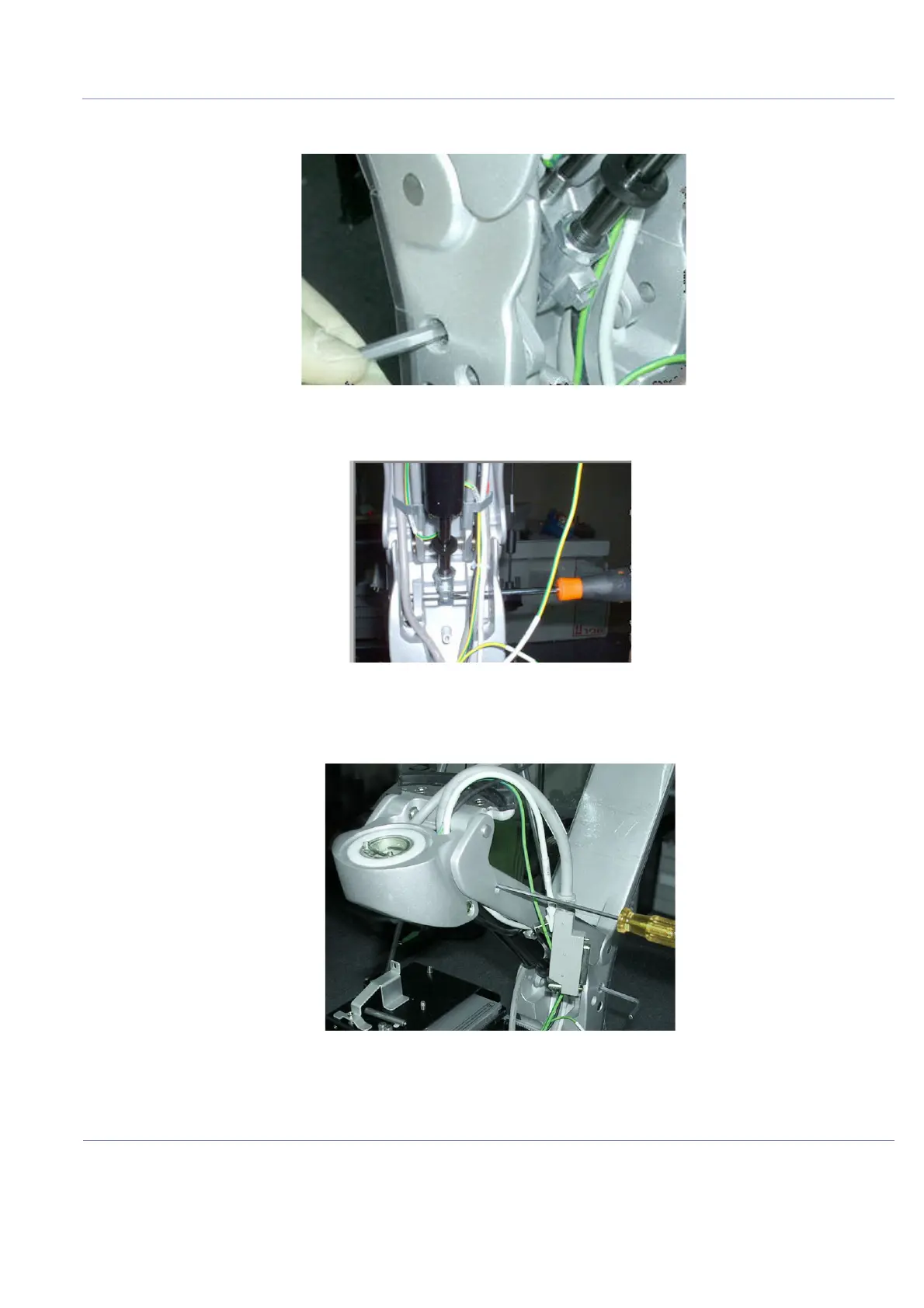
3.) Using the 5 mm Allen key, unscrew each locking screw on either side of the support arm
- Figure 8-195.
4.) Tap out the internal supporting pin using a punch - Figure 8-196.
5.) Similarly, tap out the upper gas spring securing pin and use a screwdriver to support
the joint - Figure 8-197.
6.) Carefully release the upper end of the gas spring, then the lower end of the gas spring to withdraw
the gas spring from its location.
7.) Remove the gas spring cable from its holder on the gas spring.
Figure 8-195 Releasing the Securing Screws on Either Side of the Support Arm
Figure 8-196 Tapping out the Lower Support Pin using a Punch
Figure 8-197 Supporting the Upper Gas Spring Bracket with a Screwdriver

 Loading...


