D
IRECTION FR091521, REVISION 1 VIVID S60N/VIVID S70N BASIC SERVICE MANUAL
8-188 Section 8-8 - Peripherals - Replacement Procedures
PRELIMINARY
3.) Disconnect the USB cable and the power cable from the rear of the Black and White Printer, as
shown in Figure 8-214.
4.) Carefully push the Black and White Printer out of the compartment, while holding it firmly to prevent
it from falling.
5.) Remove the printer and place it on a flat, stable surface.
8-8-2-5 Black and White Printer Installation Procedure
1.) Carefully place the replacement Black and White Printer into the compartment. Slide it all the way
in, making sure it is properly seated against the rear of the compartment.
2.) Re-connect the USB cable and the power cable to the rear of the printer - refer to, as indicated in
Figure 8-214.
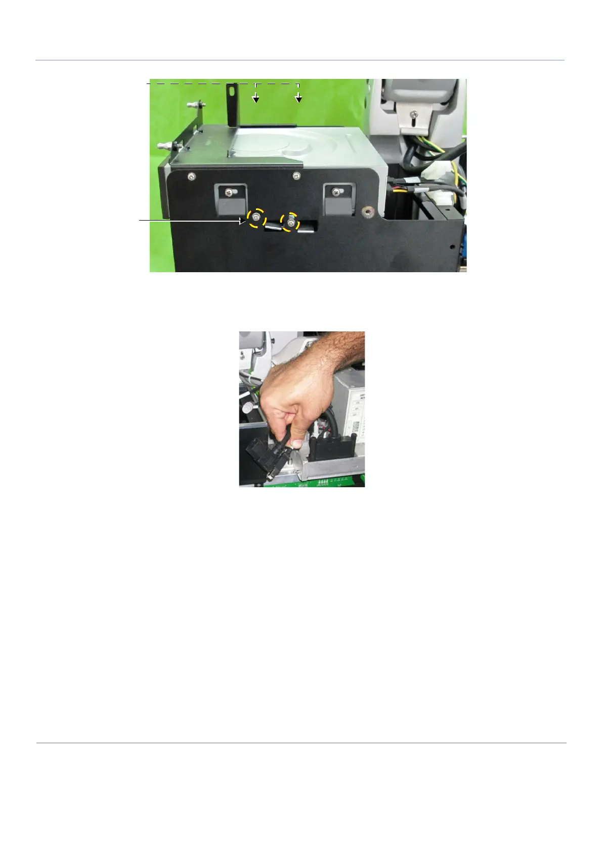
3.) Tighten the two lower Phillips screws previously released from either side of the Peripherals
Console (refer to Figure 8-213). Make sure the printer is firmly secured in position.
Figure 8-213 Screws Securing Black and White Printer in Compartment
Figure 8-214 Cables Disconnected from Rear of Black and White Printer
Screws this side
not visible in
illustration
Printer securing
screws

 Loading...


