20
────────────────────────────────────────────────────
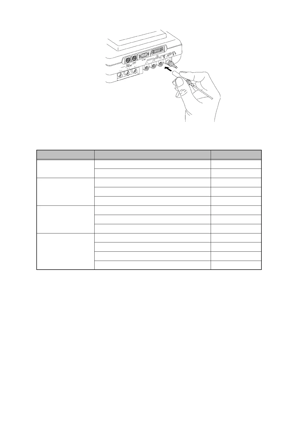
3.2 Connecting the Voltage Cords
────────────────────────────────────────────────────
Voltage Cord Connections
Line being measure
Input voltage connectors used (color code) Voltage cord use
Single-phase,
two-wire
N connector (black) Black cord
No. 1 connector (red) Red cord
Single-phase,
three-wire
N connector (black) Black cord
No. 1 connector (red) Red cord
No. 2 connector (yellow) Yellow cord
Three-phase,
three-wire
N connector (black) Black cord
No. 1 connector (red) Red cord
No. 2 connector (yellow) Yellow cord
Three-phase,
four-wire
N connector (black) Black cord
No. 1 connector (red) Red cord
No. 2 connector (yellow) Yellow cord
No. 3 connector (blue) Blue cord
2. When disconnecting a voltage cord, grasp both the voltage cord plug and the
power meter, and pull the plug out.
(2) When using the voltage cord locks
1. Install voltage cord locks for each of the voltage cords required for the type of
line being measured.