35
────────────────────────────────────────────────────
4.4 Wiring Settings and Wiring Methods
────────────────────────────────────────────────────
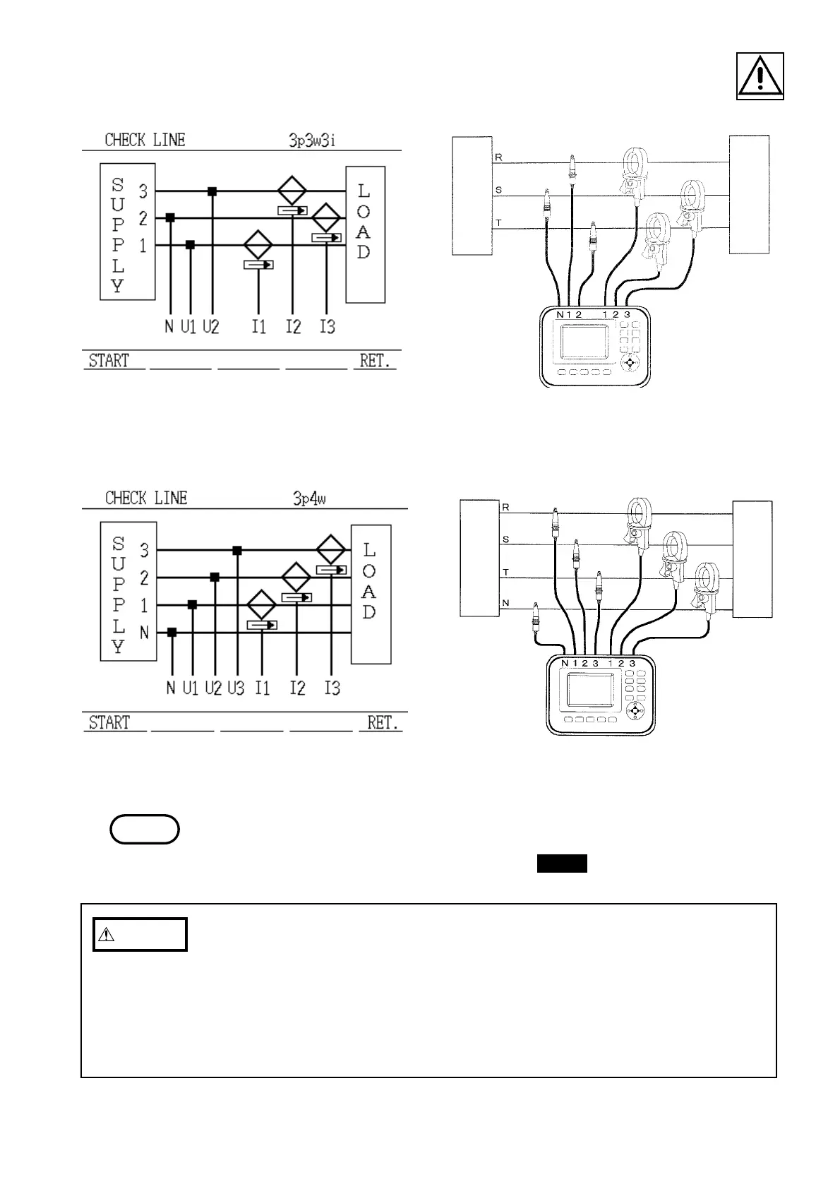
Wiring Diagram Display (Three-phase,
Three-wire, Three-current Measurement)
Re
Loa
Power
supply
Blac
Wiring Diagram (Three-phase,
Three-wire, Three-current Measurement)
Wiring Diagram Display
(Three-phase, Four-wire)
supply
Wiring Diagram (Three-phase, Four-wire)
NOTE
CAUTIO
・Although this power meter can by itself measure lines ranging from single-
phase, two-wire lines to three-phase, four-wire lines, the channels are not
independent of each other, so this power meter can not be used as three
single-phase power meters.
・When measuring a three-phase line, connect the wiring so that the phase
sequence of the line being measured matches the phase sequence of the
measurement channels of the 3166.
・In order to take accurate measurements, it is essential that the wiring setting
and the actual wiring be correct.
・Make the wiring settings before pressing the CHECK key.