36
────────────────────────────────────────────────────
4.4 Wiring Settings and Wiring Methods
────────────────────────────────────────────────────
Loa
Power suppl
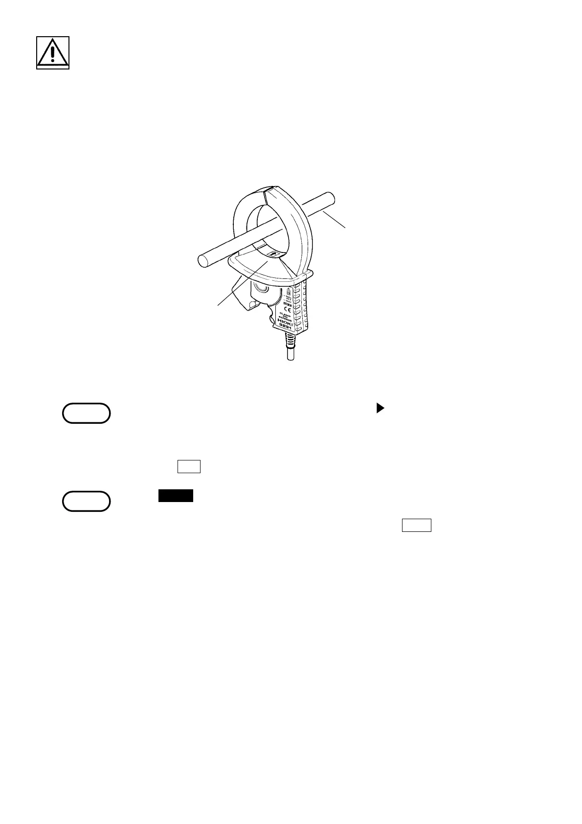
Line being measure
Arrow
Direction of the Clamp on Sensor
NOTE
NOTE
6. Connect the voltage cords and clamp on sensors to the line being measured as
indicated in the wiring diagram.
Securely clip the voltage cords onto a metallic portion of the electrical wire
from which the voltage can be read.
Clamp the clamp on sensors onto the sheathing of the electrical wire with the
arrow on the clamp pointing towards the load in accordance with the voltage
channel.
With the 9298 CLAMP ON SENSOR, the mark "
" is used. When clamping,
direct the arrowhead toward the load.
7. After the wiring is completed, perform the incorrect wiring check.
Press the
RET. function key to return to the measurement screen.
If the CHECK key is pressed while the "Instantaneous Value" screen is
displayed and the display returns to the "Wiring Check" screen, the current
minimum and maximum values is retained, but if the
EXEC. function key is
pressed, the data gathered up to that point is cleared.