5.1 About ANALYZER function
149
5
Chapter 5 ANALYZER Function (IM3533-01)
The ANALYZER function allows you to perform measurement while sweeping the measurement frequency,
signal level, and DC bias level.
Use this function for measuring frequency characteristics.
When the instrument is turned back on, the screen will display the measurement mode in use when it was last
turned off. For details on the screen configuration, refer to page 18.
ANALYZER Function
(IM3533-01) Chapter 5
5.1 About ANALYZER function
• The settings are synchronized between LCR mode, ANALYZER mode, and TRANS mode.
• DC resistance measurement is not supported in ANALYZER mode.
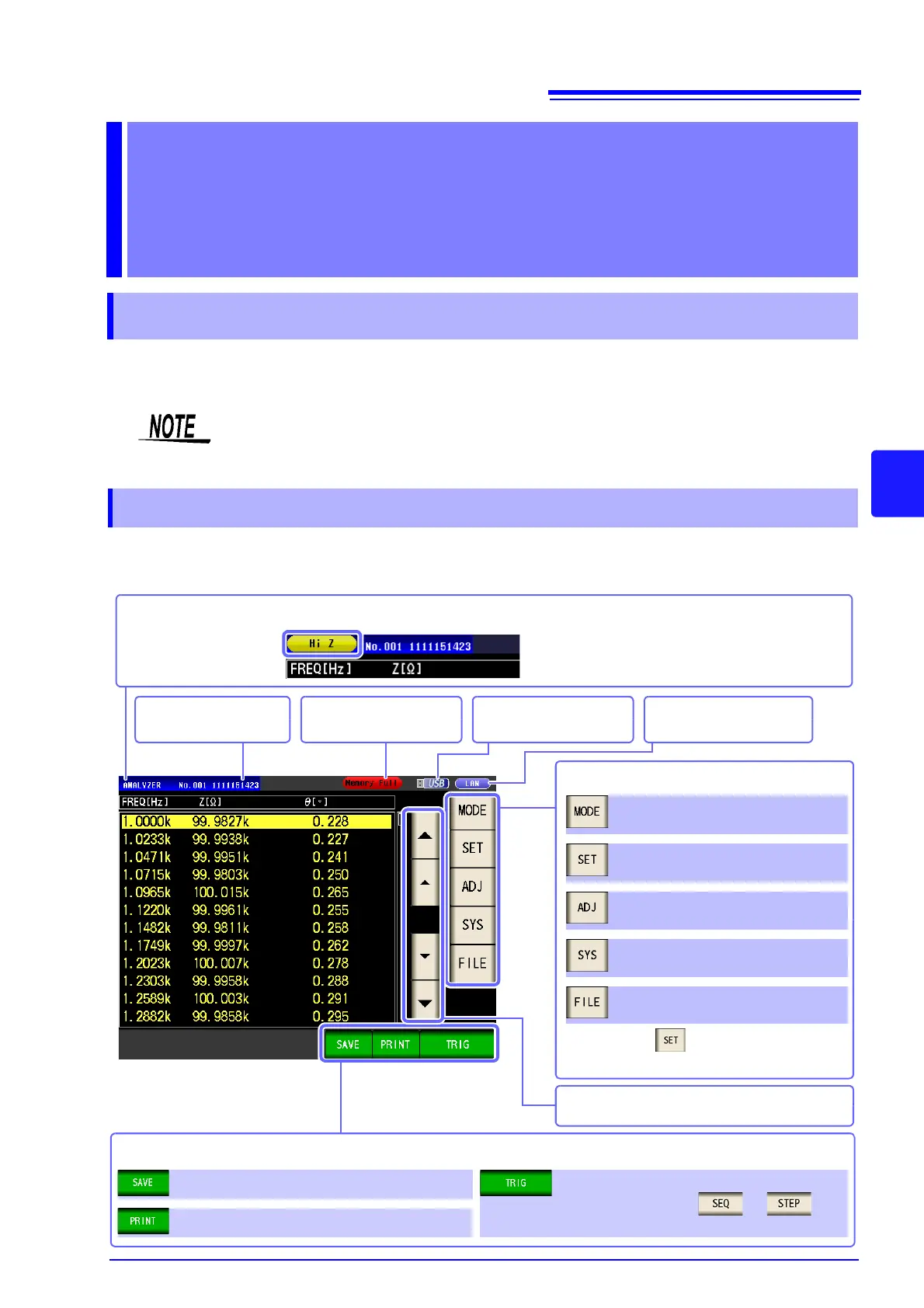
5.1.1 Measurement screen
The settings of differ depending on the
measurement mode.
Menu keys
Select the measurement mode (p. 13).
Set the details (p. 150).
Set the compensation (p. 215).
Set the system (p. 263).
Set the save settings (p. 273).
Scrolls through the list.
Indicates the name of the
loaded panel (p. 256).
Indicates the usage status
of internal memory (p. 138).
Indicates that a USB flash
drive is connected (p. 273).
Indicates the interface that is
currently set (p. 263).
If a HIGH-Z error, constant voltage measurement or constant current measurement error, or contact check error occurs, an error will
be displayed.
Example: HIGH-Z error
An operation key is displayed depending on the situation.
Operation keys
Save the measurement data (p. 277).
Print the measurement data (p. 331).
Measurement starts (p. 151).
(This is displayed when or is
selected for the trigger setting.)