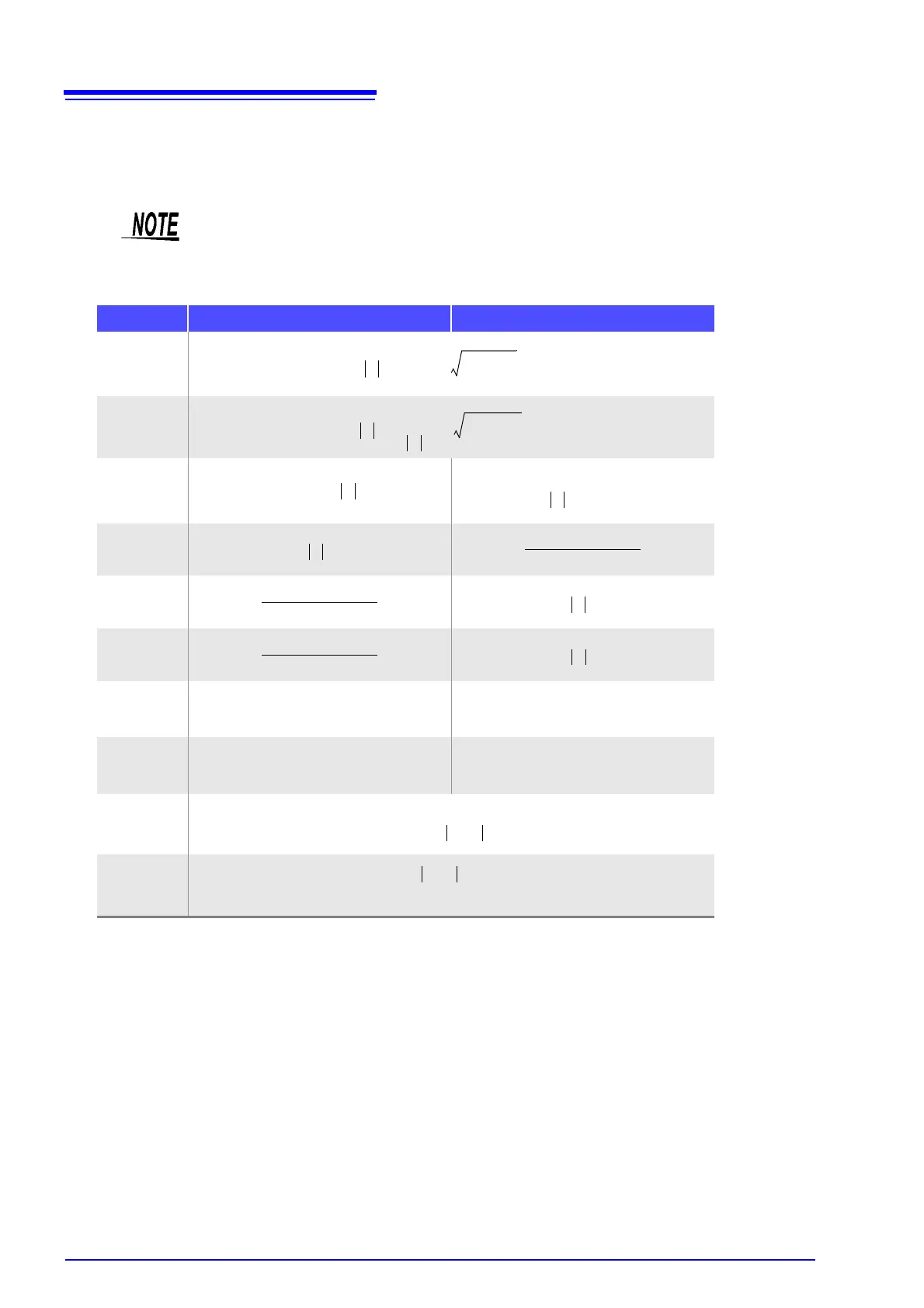
Appendix1 Measurement Parameters and Calculation Formula
A2
From the voltage V which is applied between the terminals of the sample under test, the current I which
flows through the test sample at this time, the phase angle
between this voltage V and this current I,
and the angular velocity
which corresponds to the measurement frequency.
*
: phase angle of admittance Y (
= -
)
Ls, Rs, Cs: The measured values of L, C, and R in series equivalent circuit mode.
Lp, Rp, Cp: The measured values of L, C, and R in parallel equivalent circuit mode.
The phase angle
is shown based on the impedance Z. When measuring based on the
admittance
Y, the sign of the phase angle
must be reversed.
Item Series equivalent circuit mode Parallel equivalent circuit mode
Z
Y
R
X
G
B
L
C
D
Q
R
P
1
Y
cos
------------------
1
G
----=
=
*
Q
sin
cos
--------------
1
D
----=
=