4.3 Setting DC Resistance Measurement
80
The DC resistance Rdc can be measured by outputting a 2.0 V (fixed) DC signal. The measurement process
is as follows:
1. Measure the DC resistance with an applied voltage of 2.0 V.
2. Measure the DC resistance with an applied voltage of 0 V and use the result as the offset value.
3. Using the offset value, reduce the measurement error.
4. Output the Rdc measurement value.
4.3 Setting DC Resistance Measurement
• It is necessary to set the line frequency for the power supply being used so that the instru-
ment can reject noise. Set this parameter to the frequency of the commercial power sup-
ply being used before using the instrument to make measurements. Failure to properly set
the line frequency will prevent you from acquiring stable measurement values.
See"4.3.4 Setting the Line Frequency" (p. 87)
• To measure DC resistance, you need to set Rdc in the measurement parameters beforehand.
See "1.3.7 Parameter Settings Screen" (p. 28), "4.1.2 Setting Display Parameters" (p. 47)
• When Rdc and other parameters are set, the DC resistance is measured after those other
parameters have been measured with the AC signal. The measurement conditions can be
set individually.
• The DC bias function cannot be enabled when DC resistance measurement is performed.
• When the sample is a capacitor, it may not be possible to perform DC resistance mea-
surement normally.
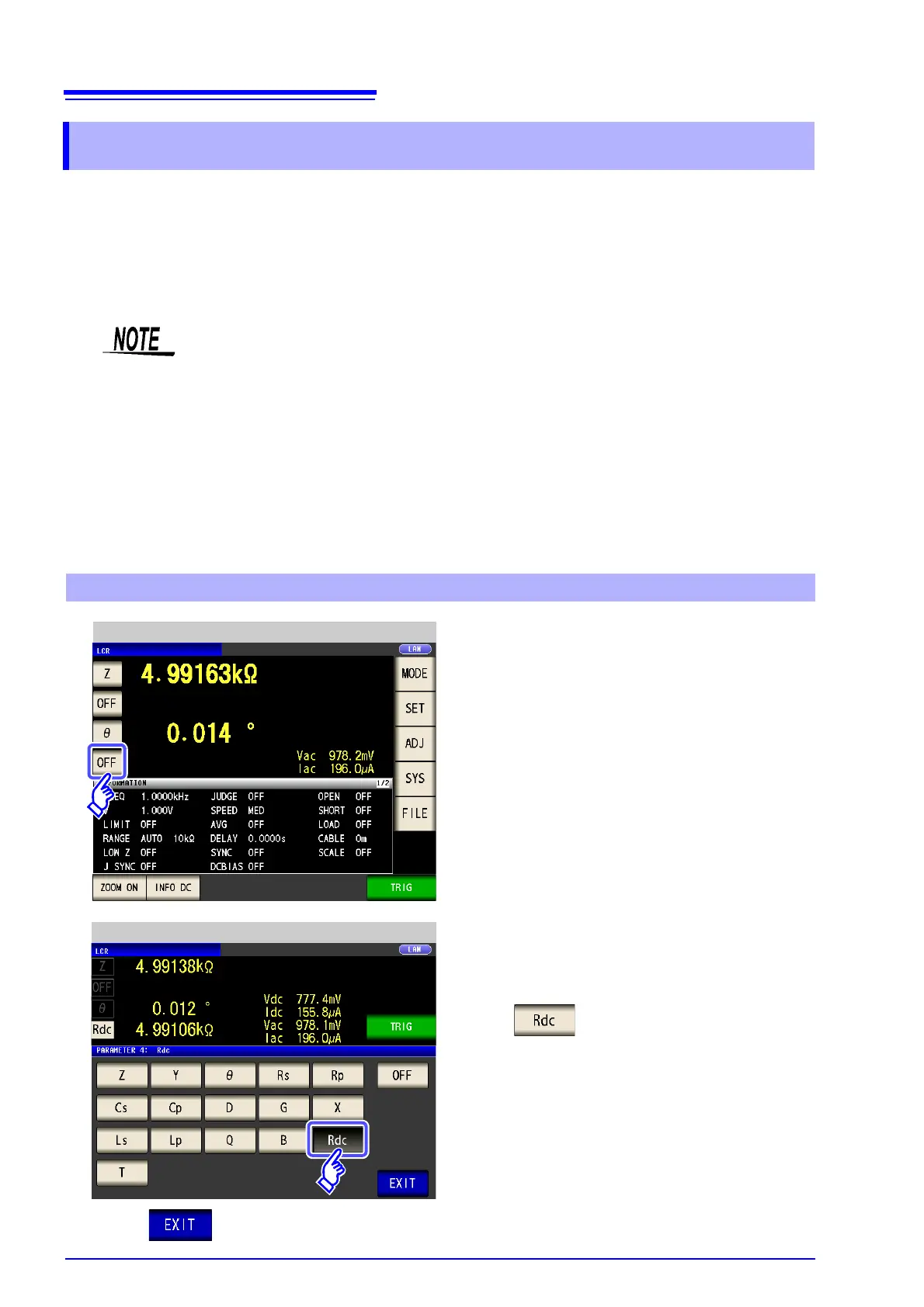
Adding Rdc to Measurement Parameters
LCR Measurement Screen
1
Select the parameter you want to change.
2
Press .
Parameter Setting
3
Press to close the setting screen.