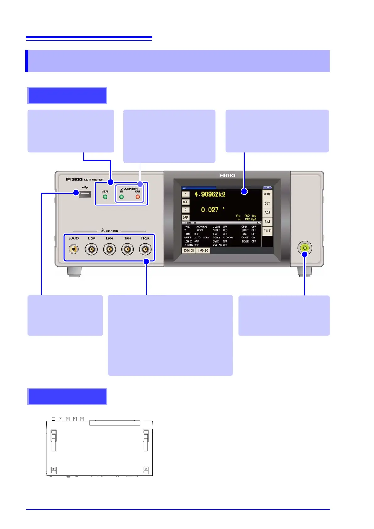
Front
Measurement LEDs
Lights during measurement.
Standby Key
Toggle standby state (p. 35)
(The main power switch is located
at the rear.)
Front USB connecter
Connect a USB flash drive
storage device. (p. 274)
Measurement Terminals
Connect measurement cables or a fixture. (p. 32)
•H
CUR
jack: Current source terminal
•H
POT
jack: Detected voltage high terminal
•L
POT
jack: Detected voltage low terminal
•L
CUR
jack: Measurement current detected
terminal
• GUARD jack: Shield (measurement
ground) terminal
LCD Display
This is a touch panel display.
Press the keys displayed on the
screen to operate the instrument.
Judgment Result
Indication LEDs
Indicates the judgment results for
comparator and BIN measurement.
LCR mode (p. 102)
TRANSFORMER mode (p. 193)
(Example: IM3533)
This instrument can be rack mounted.
See "Appendix10 Rack Mounting"(p. A15)
Parts removed from this instrument should be
stored in a safe place to enable future reuse.
Bottom Panel