3.1 When LCR Mode
37
3
Chapter 3 Measurement Example
This chapter provides example measurement scenarios for LCR mode, ANALYZER mode (IM3533-01 only),
and TRANSFORMER mode.
Necessary items: 9263 SMD test fixture, Laminated ceramic capacity you want to measure
Measurement
Example Chapter 3
3.1 When LCR Mode
Measuring a Laminated Ceramic Capacitor
1
Connect the 9263 SMD test fixture to the measurement terminals.
For the connection procedure, refer to the
instruction manual supplied with the fixture.
2
Set the first parameter to Cs and the third parameter to D. (p. 46)
Trigger synchronous output function
setting: OFF (p. 77)
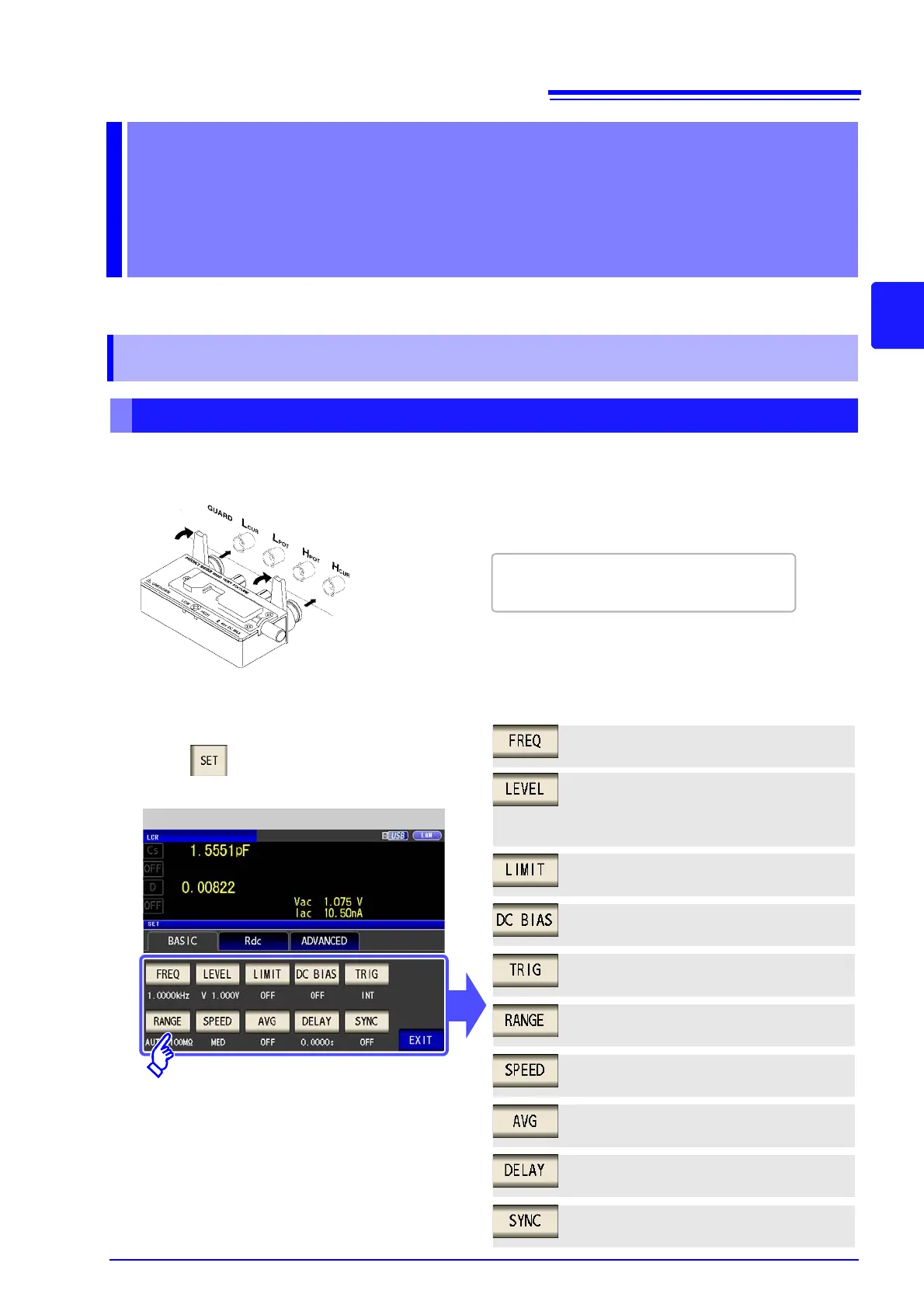
3
Set the measurement conditions.
Touch on the Measurement screen, select
the item you want to set, and set it as follows.
LCR Basic Settings
Measurement frequency: 1.0000 kHz
(p. 50)
Measurement signal mode:
Open circuit voltage (V) mode (p. 52)
Measurement signal level: 1.000 V (p. 52)
Measurement range: AUTO (p. 62)
Measurement speed: MED (p. 73)
Voltage and current limit: (p. 56)
Average: OFF (p. 74)
Trigger delay: 0.0000 s (p. 76)
Trigger: INT(p. 60)
DC bias: OFF (p. 58)