Appendix
Appendix5 Supplying DC Bias
A9
When you want to apply a DC current bias, refer to the following explanation.
With regards to a DC current bias for a transformer, choke coil, or other test sample, configure the external
bias circuit as shown below.
• Connect the sample to the measuring probe and then gradually raise the voltage of the DC source to the
specified DC bias level. To disconnect the sample, gradually reduce the voltage of the DC source until the
DC bias supplied to the sample is decreased to zero. You may disconnect the sample after this is achieved.
• Use a choke coil (CH) which has a large enough impedance with reference to the sample under test (Z).
•A H
CUR
side capacitor must have a small enough impedance (i.e. a large enough capacitance) relative to
the output resistance (100 ) while a H
POT
capacitor must have a small enough impedance to the R
HP
.
• Be careful about the polarity when connecting together the probes, the sample to be tested, and the DC cur-
rent source.
• Be careful not to magnetically saturate the choke coil (CH) with the DC bias current.
• It takes a little time for the DC current which is being supplied to the sample under test to reach the set
value, so you should wait for a certain stabilization time period (which depends upon the sample) before
performing testing. Be careful, because if you perform testing before this stabilization time period has
elapsed, the results will not be reliable.
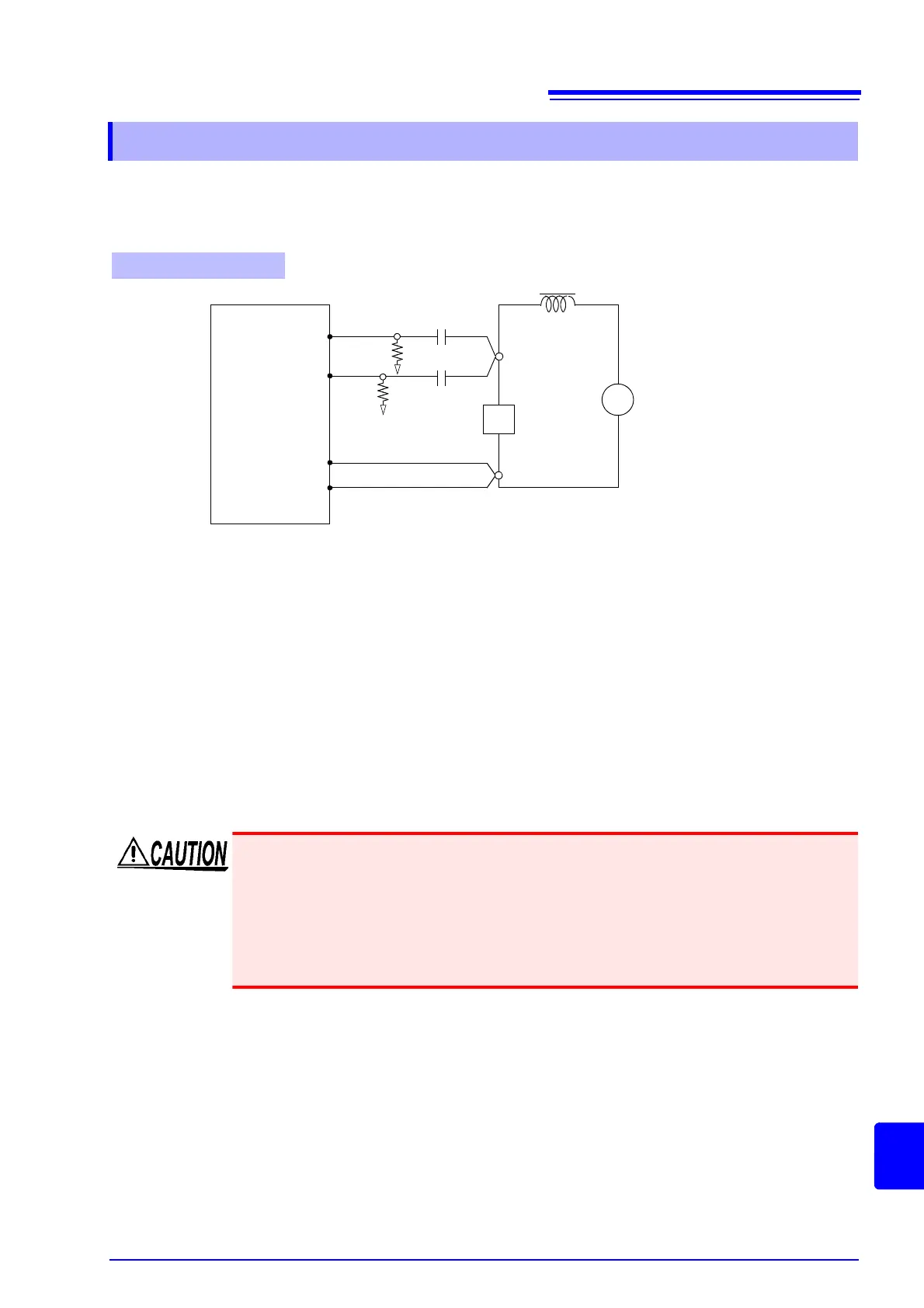
Appendix5.2 How to Supply a DC Bias Current
DC Bias Current Circuit
IM3533
Capacitor
C
HC
C
HP
Z
+
-
H
CUR
H
POT
L
POT
L
CUR
Sample to be tested
R
HP
R
HC
+
-
DC current source
Choke coil
CH
• In order to avoid electric shock accident, be absolutely sure not to touch the test termi-
nals while the DC bias is being supplied to them.
• Due to the inductance of the coil and the sample, counter electromotive force is generated when
the sample is removed or inserted with the DC bias supplied. This may result in damage to the
instrument or to the DC source.
• When measuring the element whose DC resistance is high (incl. open state), a high volt-
age occurred on the H side may cause damage on the main instrument.