13.1 Connecting the Printer
332
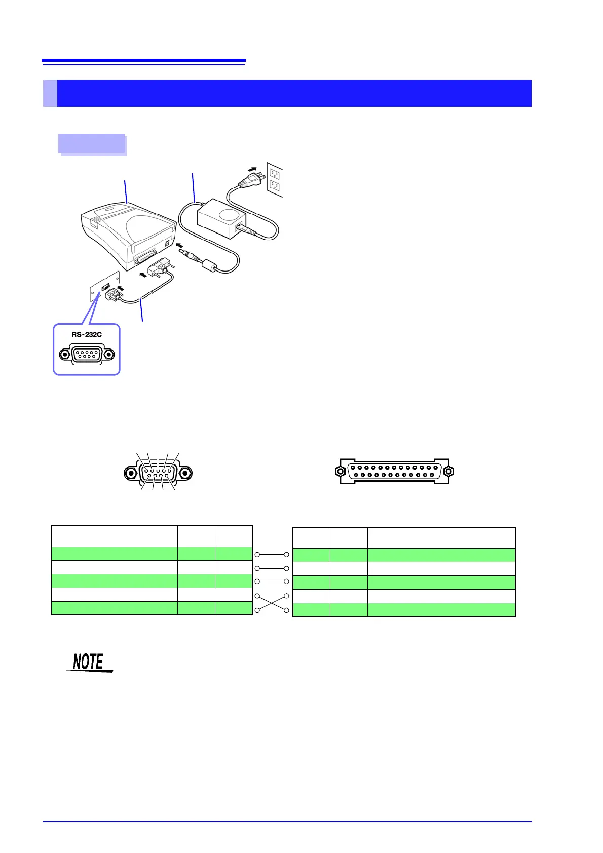
Connecting the Printer to the Instrument
Procedure
2
3
Printer
AC Adapter
RS-232C Cable
1
Confirm that the instrument and Printer are
turned off.
2
Connect the AC Adapter to the Printer, and insert
the power plug into an outlet.
3
Connect the RS-232C Cable to the RS-232C
connectors on the instrument and printer.
4
Turn the instrument and printer on.
Rear
25 ....................... 14
Printer Connector (25-pin)
Z3001 RS-232C interface connector (9-pin)
Pin
Signal
Name
Function
2 TxD
Transmit Data
3 RxD
Receive Data
7 GND
Signal or Common Ground
4 RTS
Request to Send
5 CTS
Clear to Send
Function
Signal
Name
Pin
Receive Data
RxD 2
Transmit Data
TxD 3
Signal or Common Ground
GND 5
Request to Send
RTS 7
Clear to Send
CTS 8
6 7 8 9
1 2 3 4 5
Connector pin assignments
13 ....................... 1
• To use hardware flow control, you will need an RS-232C cable whose RTS and CTS wires
are connected (7-pin at instrument to 5-pin at printer or 8-pin at instrument to 4-pin at
printer). Hardware flow control cannot be used with cables whose RTS and CTS wires are
shorted together.
• When using a printer other than the recommended model, exercise care to choose a
model with compatible connector pin assignments.