2.4 Connecting the Measurement Cables, Probes, or Fixture
32
Be sure to read the "About Handling of Cords, Fixtures and Temperature
probes" (p. 7) before connecting measurement cables, probes or test fixture.
Connect your measurement cables, optional Hioki probes or test fixture to the measurement terminals.
Refer to
"Options" (p. 2) for details.
See the instructions provided with the fixture for operating details.
2.4 Connecting the Measurement
Cables, Probes, or Fixture
• Basically, when you make a probe yourself, it may not be able to satisfy the specifications
of this instrument.
See: "Options" (p. 2)
• If all four terminals are disconnected, a meaningless number may be displayed on the
unit.
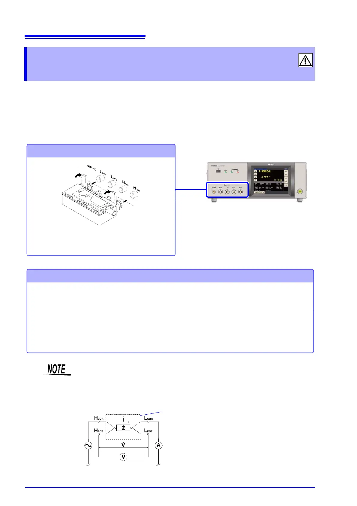
Connecting a measurement cable/fixture
Connect directly to the measurement jacks with
the label side up, and affix with the levers on the
left and right.
Points to pay attention to when making your own probe
• Use 50 coaxial cable for the measurement cable.
• Ensure that the length of the cable is the same as that set for the instrument.
(IM3533: 1 m, IM3533-01: 1 m/ 2 m/ 4 m)
• The cable length is defined as the length from the tip of the BNC connector to the tip of the probe electrode.
• Make the portion of the core wire that is exposed as short as possible.
• Connect the H
CUR
, L
CUR
, H
POT
, and L
POT
shield pairs at the measurement object side.
(Ensure that a shield is not connected to a core wire.)
Measurement Terminal
Configuration
Fixture
Normal mode