8.1 Setting Open Circuit Compensation
215
8
Chapter 8 Error Compensation
Compensate for errors caused by a fixture or measurement cable.
With open circuit compensation, it is possible to reduce the influence of the floating impedance of the test
cables and thereby to enhance the accuracy of measurement. It is effective for test samples whose imped-
ance is relatively high. The comparator decision mode can be set as one of the following:
Error
Compensation Chapter 8
8.1 Setting Open Circuit Compensation
All Compensation
The compensation values are obtained for all test frequencies (p. 216).
The range of measurement frequencies to compensate can be set.
"Compensation range limitation function" (p. 218)
Spot Compensation
The compensation values are obtained at the set measurement fre-
quency only (p. 216).
OFF
Open circuit compensation data becomes invalid (p. 223).
• Before open circuit compensation, always set the cable length.
See"8.4 Compensating Measurement Cable Errors (Cable Length Compensation)" (p. 245)
• The measurement accuracy values defined in the specifications are for when open circuit
compensation and short circuit compensation are performed.
• Be sure to perform compensation again after replacing the measuring cable.
You will be unable to obtain correct values if measurement is performed in the compensa-
tion state prior to replacement.
• For SPOT compensation, the open circuit compensation will be valid only when the mea-
surement frequency agrees with the SPOT compensation frequency.
• When performing compensation, make sure that there is no noise source nearby. Noise
may cause an error when performing compensation.
ex. Servo Motor, switching power source, high-voltage cable and etc.
• For SPOT compensation, the open circuit compensation will be valid only when the mea-
surement frequency agrees with the SPOT compensation frequency.
• The compensated value is preserved in the memory of the main instrument even when
power is turned off.
• If the setting of the low Z high accuracy mode is changed, the compensation value
becomes invalid. Select the low Z high accuracy mode setting before compensation.
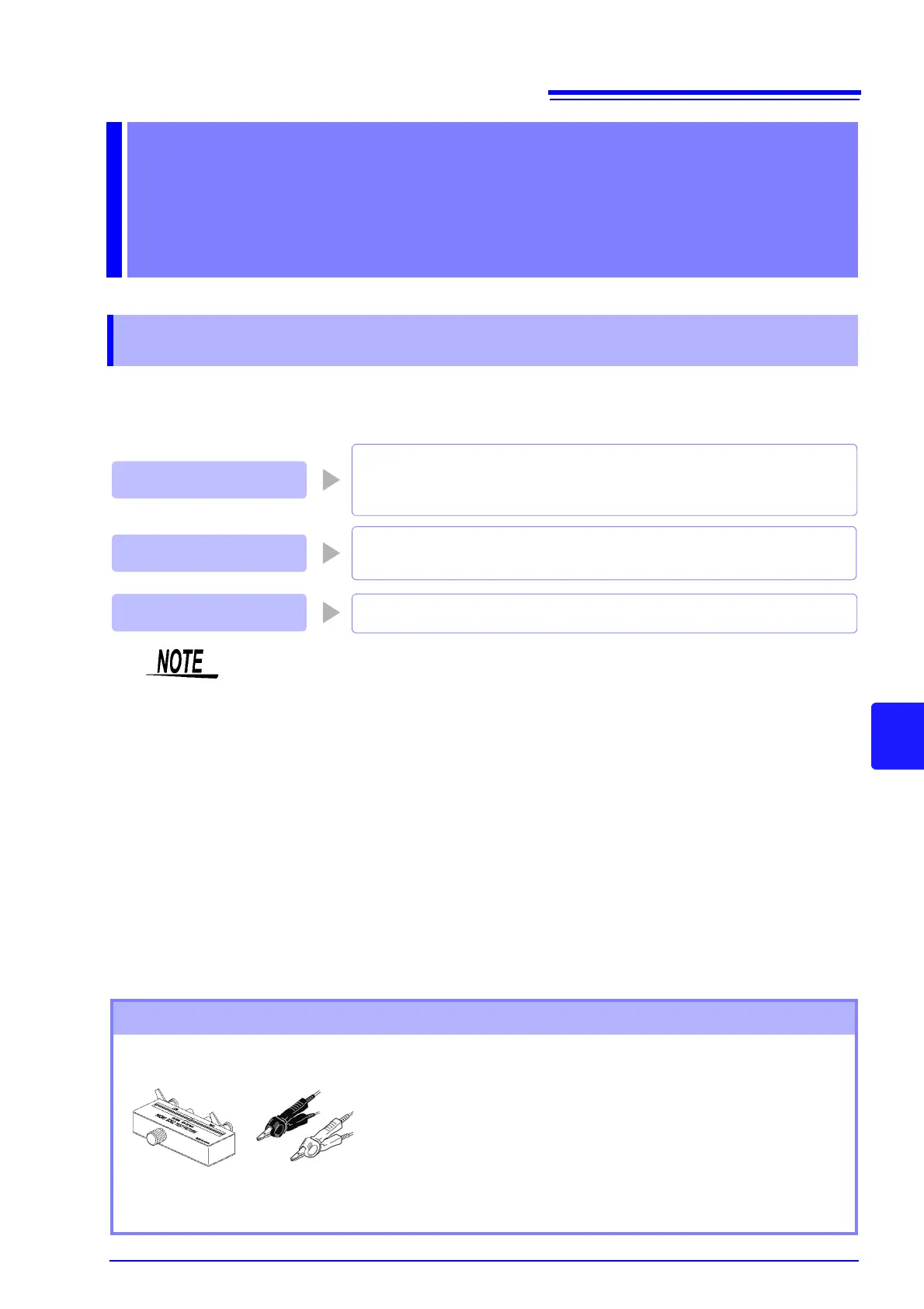
Before Performing Screen Operations
• Arrange the test leads as they will be when measurement will actu-
ally be performed. Changing the configuration of the leads may
result in compensation not being performed properly.
• Create an open state between the HIGH terminals and LOW termi-
nals of the probes or fixture in accordance with the width of the
measurement object. (Connect H
CUR
and H
POT
, and connect L
CUR
and L
POT.
)
• In open compensation, be sure to perform guarding.
See"Appendix2 Measurement of High Impedance Components"(p. A3)