12.2 Timing Chart
319
12
Chapter 12 External Control
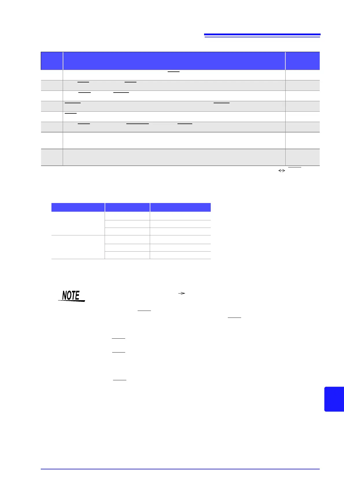
Timing Chart Interval Descriptions
*1: There is an approximate error of 100 s in the delay time entered for Judgement Result EOM
for the
setting value. t1 is the reference value for when the setting value is 0.0000 s.
*2: t2 is the reference value for when trigger input for during measurement is disabled (p. 136).
*3: When the panel number is read by the panel load function, the response time is as shown in the table
below.
• When the trigger synchronous output function and trigger delay is enabled, wait times are included.
*4: Reference value for Measurement frequency: 1 kHz, Measurement speed: FAST,
Measurement range: HOLD (p. 350)
Interval Description
Time
(Approximate)
t1 From Comparator, BIN Judgement Result to EOM (LOW): Setting value for delay time *
1
40 s
t2 From EOM width (LOW) to TRIG (LOW): Minimum time from end of measurement to next trigger *
2
400 s
t3 From TRIG
(LOW) to INDEX (HIGH): Time from trigger to circuit response *
3
1 ms
t4 INDEX width (HIGH): Minimum chuck time, switching chuck with INDEX (LOW) is possible *
4
1 ms
t5 EOM width (HIGH): Measurement time *
4
2 ms
t6 From TRIG width (LOW) to LD-VALID (HIGH) and CALIB (HIGH): Time to recognize panel number t3
t7 Trigger pulse width (LOW time)
At least
100 s
t8 Trigger off (HI time)
At least
100 s
• Since the speed of the rise (LOW HIGH) of the comparator/BIN judgment result differs
depending on the configuration of the circuit connected to the EXT I/O, there is the likeli-
hood of an incorrect judgment if the level of the comparator/BIN judgment result acquired
immediately after EOM
output is used. To prevent this from happening, a delay time (t1)
between the comparator/BIN judgment result and the EOM
can be set. Furthermore, if the
judgment result signal line of the EXT I/O is set to be reset simultaneously with the mea-
surement start signal, and a forced transition to the HIGH level is performed at the same
time as TRIG
, the transition from LOW to HIGH does not occur when the judgment result
is output after measurement ends. As a result, the delay time between the judgment result
and the EOM
can be set to the minimum level. However, be careful because the judgment
result confirmation interval is until the next trigger is accepted.
• During measurement, a trigger input from EXT /IO or communicating by interface may
lead to a bigger dispersion of delay time between comparator or BIN judgement result out-
put and EOM
. As far as possible, try not to control from external sources when carrying
out measurement.
See "Setting the Delay Time from the Output of Comparator and BIN Judgment Results until Output of
EOM (LOW) and Resetting Judgment Results" (p. 134)
LCR Application Disk - communication commands (
:IO:OUTPut:DELay), (:IO:RE-
Sult:RESet)
Measurement mode Load mode Response time
LCR
LCR+ADJ 10 ms
HARD 9 ms
ADJ 4 ms
ANALYZER
ANA+ADJ 80 ms
HARD 60 ms
ADJ 6 ms