15.3 Error display
361
Chapter 15 Maintenance and Service
15
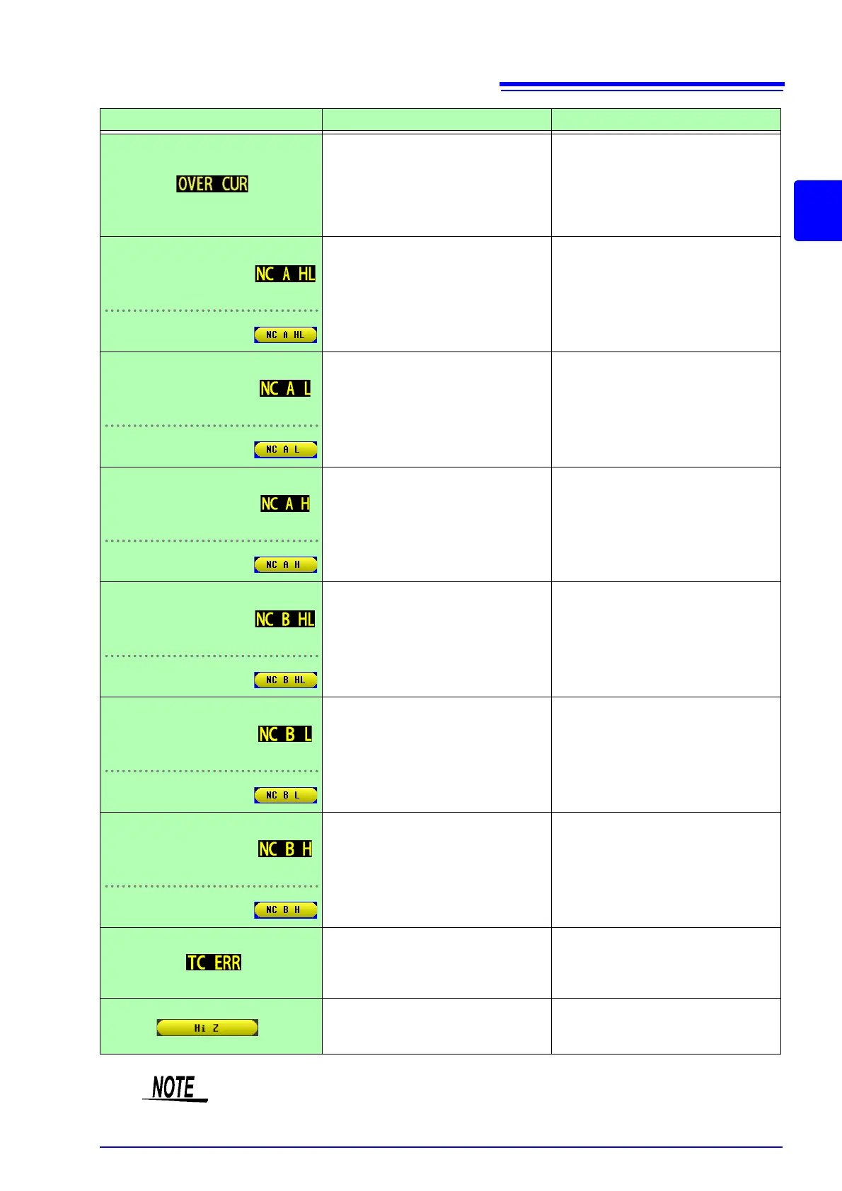
This is displayed when an overcurrent is
detected while the DC bias setting is on.
• Because the instrument’s H
CUR
ter-
minal output switch has been turned
off, no current will flow. To resume
measurement, input a trigger.
• Check the DC bias setting or the sam-
ple's voltage and impedance (p. 58).
When LCR mode,
TRANSFORMER mode,
CONTINUOUS measure-
ment mode:
This is displayed when the H
POT
, H
CUR
,
L
POT
, or L
CUR
terminal is not connected
after measurement, for example due to
a break in wiring.
Check the connection of each terminal
(p. 32).
When ANALYZER mode:
When LCR mode,
TRANSFORMER mode,
CONTINUOUS measure-
ment mode:
This is displayed when the L
POT
or L
CUR
terminal is not connected after measure-
ment, for example due to a break in wir-
ing.
Check the connection of each terminal
(p. 32).
When ANALYZER mode:
When LCR mode,
TRANSFORMER mode,
CONTINUOUS measure-
ment mode:
This is displayed when the H
POT
or
H
CUR
terminal is not connected after
measurement, for example due to a
break in wiring.
Check the connection of each terminal
(p. 32).
When ANALYZER mode:
When LCR mode,
TRANSFORMER mode,
CONTINUOUS measure-
ment mode:
This is displayed when the H
POT
, H
CUR
,
L
POT
, or L
CUR
terminal is not connected
after measurement, for example due to
a break in wiring.
Check the connection of each terminal
(p. 32).
When ANALYZER mode:
When LCR mode,
TRANSFORMER mode,
CONTINUOUS measure-
ment mode:
This is displayed when the L
POT
or L
CUR
terminal is not connected prior to mea-
surement, for example due to a break in
wiring.
Check the connection of each terminal
(p. 32).
When ANALYZER mode:
When LCR mode,
TRANSFORMER mode,
CONTINUOUS measure-
ment mode:
This is displayed when the H
POT
or
H
CUR
terminal is not connected prior to
measurement, for example due to a
break in wiring.
Check the connection of each terminal
(p. 32).
When ANALYZER mode:
This is displayed when the instrument is
unable to perform temperature correc-
tion.
• Check the temperature probe con-
nection (p. 33).
• Check the reference temperature and
temperature coefficient settings (p. 81).
This is displayed when a measurement re-
sult is high in relation to the judgment ref-
erence set for the HIGH-Z reject function.
Check the connection of each terminal
(p. 130).
Error display Description Remedy and Reference
Since impedance is measured internally even when measuring only temperature, imped-
ance error output may be encountered.