3.7 Address Configuration
A3-37
ME0384-4A
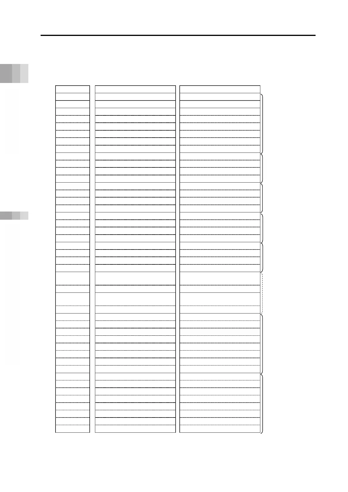
[For DeviceNet]
■ DeviceNet overall address configuration example (direct numerical control mode + simple
direct mode/positioner 1 mode)
Shows direct numerical control mode connection for 2 axes and simple direct or positioner 1
mode connection for 12 axes.
RCON
PLC input
*
Power supply unit status signal 0
Power supply unit status signal 1
Power supply unit status signal 2
5
(Not available)
Power supply unit status signal 3
Power supply unit status signal 4
(Axis 0) Specified position data (L)
(Axis 0) Present position data (L)
9
(Axis 0) Specified position data (H)
(Axis 0) Present position data (H)
Positioner 1
10
(Axis 0) Command position No.
(Axis 0) Completed position No.
/simple direct mode
(Axis 1) Specified position data (L)
(Axis 1) Present position data (L)
13
(Axis 1) Specified position data (H)
(Axis 1) Present position data (H)
4 words each
(Axis 1) Command position No.
(Axis 1) Completed position No.
(Axis 2) Specified position data (L)
(Axis 2) Present position data (L)
17
(Axis 2) Specified position data (H)
(Axis 2) Present position data (H)
4 words each
(Axis 2) Command position No.
(Axis 2) Completed position No.
(Axis 3) Specified position data (L)
(Axis 3) Present position data (L)
21
(Axis 3) Specified position data (H)
(Axis 3) Present position data (H)
4 words each
(Axis 3) Command position No.
(Axis 3) Completed position No.
・
・
・
・
・
・
4 words each
・
・
・
・
・
・
(Axis 12) Specified position data (L)
(Axis 12) Present position data (L)
(Axis 12) Specified position data (H)
(Axis 12) Present position data (H)
58
(Axis 12) Specified positioning width (L)
(Axis 12) Present current value (L) *1
8 words each
(Axis 12) Specified positioning width (H)
(Axis 12) Present current value (H) *1
(Axis 12) Specified speed
(Axis 12) Present speed data
(Axis 12) Specified acceleration/deceleration
62
(Axis 12) Pushing current limit value
(Axis 12) Alarm code
(Axis 13) Specified position data (L)
(Axis 13) Present position data (L)
(Axis 13) Specified position data (H)
(Axis 13) Present position data (H)
66
(Axis 13) Specified positioning width (L)
(Axis 13) Present current value (L) *1
(Axis 13) Specified positioning width (H)
(Axis 13) Present current value (H) *1
8 words each
(Axis 13) Specified speed
(Axis 13) Present speed data
(Axis 13) Specified acceleration/deceleration
70
(Axis 13) Pushing current limit value
(Axis 13) Alarm code
* Relative CH is the CH number relative to the gateway head CH
*1 The present current value should be the command current value for the stepper motor and be the
feedback current value for the AC servomotor (including AC servomotor connected to SCON-CB).

 Loading...


