3.8 I/O Signals
A3-138
ME0384-4A
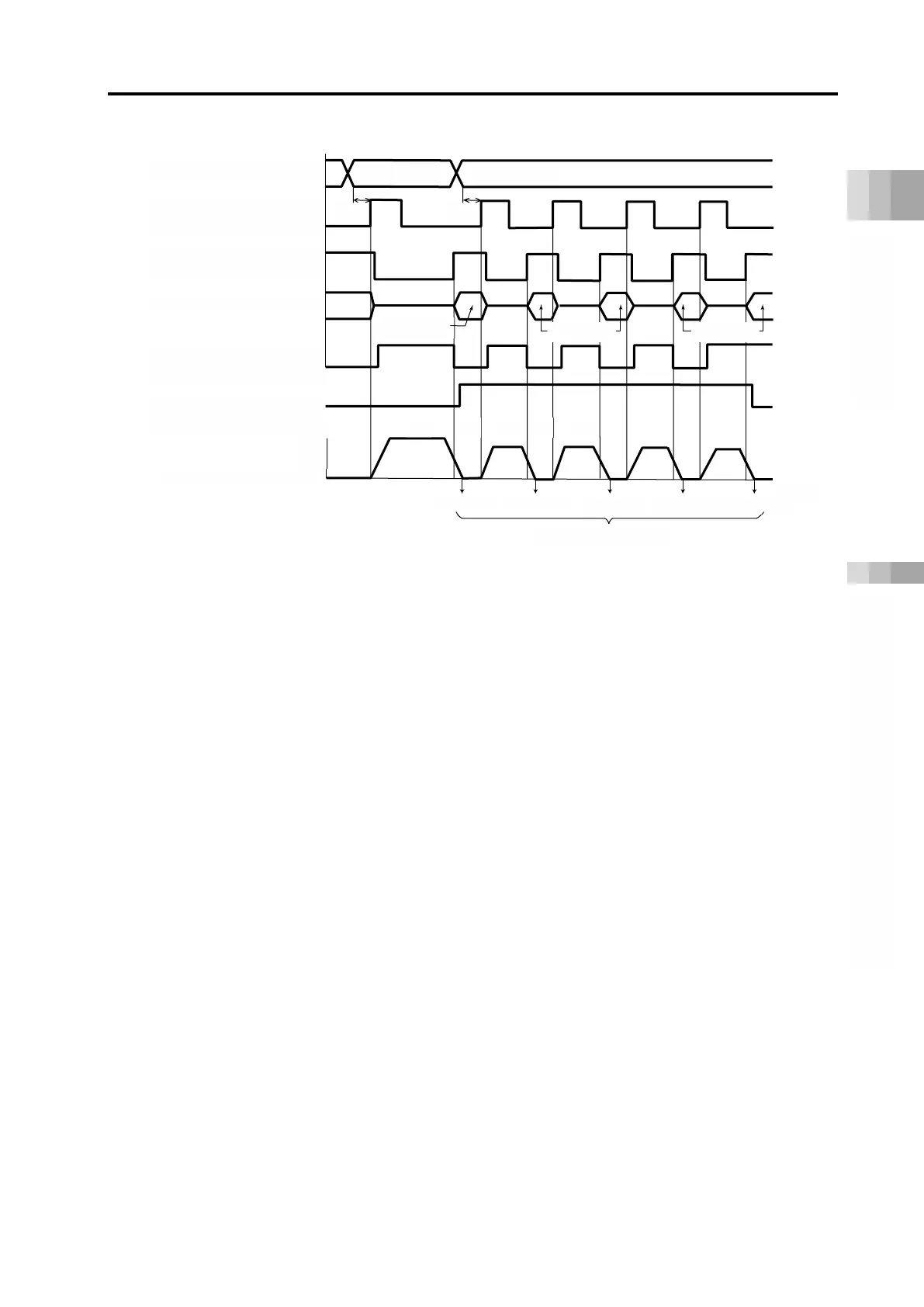
* Consider the scan time of the host controller, so that T1 ≥ 0 ms.
[Description of Operation]
(1) Positioning to position 1 (100.00 mm) is carried out
(2) When positioning to position 1 is completed, positioning complete signal PEND changes to
"1" (ON). The zone signal PZONE also changes to "1" (ON).
Switch position No. 1 → 2 and set the start signal CSTR to "1" (ON).
(3) When travel starts, PEND signal changes from "1" (ON) to "0" (OFF) and the moving signal
MOVE changes from "0" (OFF) to "1" (ON). After confirming that the PEND signal is "0"
(OFF), set the CSTR signal to "0" (OFF).
(4) After moving by 50 mm again, the PEND signal changes to "1" (ON) and the MOVE signal
changes to "0" (OFF). At this time, the travel count is counted as 1 by the PLC. Next, set the
CSTR signal for the second 50 mm movement to "1" (ON).
(5) Operations (3) and (4) below are repeated.
The PLC side confirms the state of the PZONE signal after positioning complete, and if it is "0"
(OFF), it recognizes it as the last workpiece position.
If the count on the PLC side does not match the state of the zone signal, the signal timing may
not have been synchronized.
(CSTR)
Positioning complete
(PEND)
(PZONE)

 Loading...


