3.8 I/O Signals
A3-150
ME0384-4A
[Multi-rotation Specification]
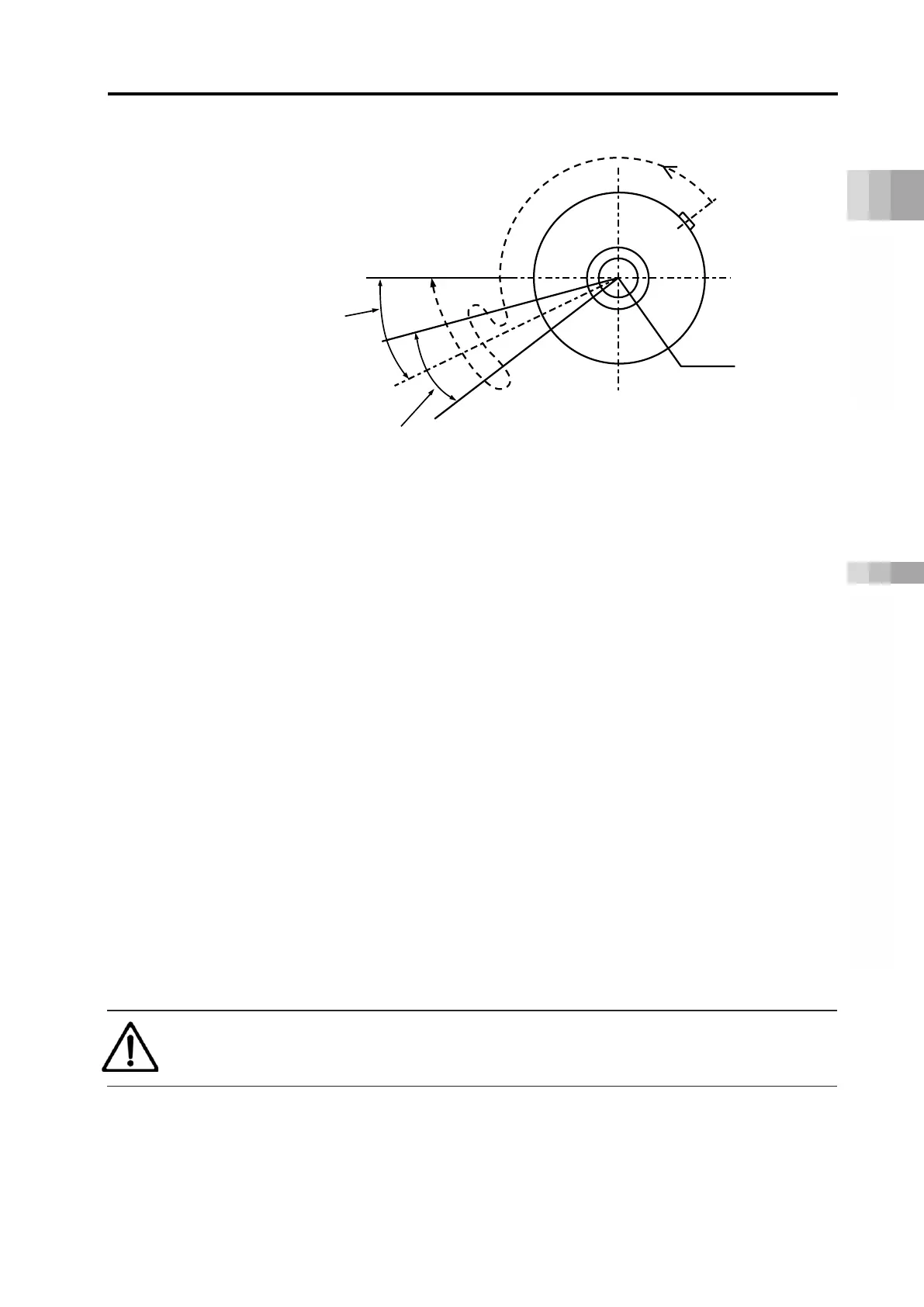
(1) When home return is commanded, the rotary part rotates in the CCW (counterclockwise)
direction as seen from the load side.
The speed is 20 deg/s.
(2) The home sensor turns ON.
(3) It travels in reverse.
(4) Confirm that the home sensor turns OFF as it returns to the position beyond the detection
range of the home sensor.
(5) It travels in reverse.
(6) Check again that the home sensor is ON.
(7) Confirm that the home sensor turns OFF beyond the detection range on the home reverse
side of the home sensor.
(8) It travels in reverse.
(9) Check that the home sensor is ON.
(10) Confirm that the home sensor turns OFF beyond the detection range on the home side of
the home sensor.
(11)
Calculate the detection range center of the home sensor from the results of (6), (7), (9) and
(10).
(12) Moves from the position of (11) for the amount set in Parameter No. 22 “Homing Offset” and
stops.
This stopped position should be the home position.
Caution
● When changing Parameter No. 22 "Homing offset", be sure to refer to page B6-16.
(5) Relation among Output Torque, Allowable Inertia Moment and Rotary Speed
Refer in the graph shown in “Appendix 2.4 Rotary Speed and Output Torque / Allowable Inertia
Moment”.
(Forward rotation side swivel end)
distance
Offset reference position
(Center of (6), (7), (9) and (10))
Home sensor detection range

 Loading...


