1.3 Startup Procedure
B1-7
ME0384-4A
1.3 Startup Procedure
When using this product for the first time, refer to the following procedure and pay attention so as
to avoid checking or wiring errors.
This section describes the startup procedure of the RCON system. For installation and wiring of
miscellaneous devices connected to the network, controllers and actuators, follow the respective
instruction manuals (DVDs).
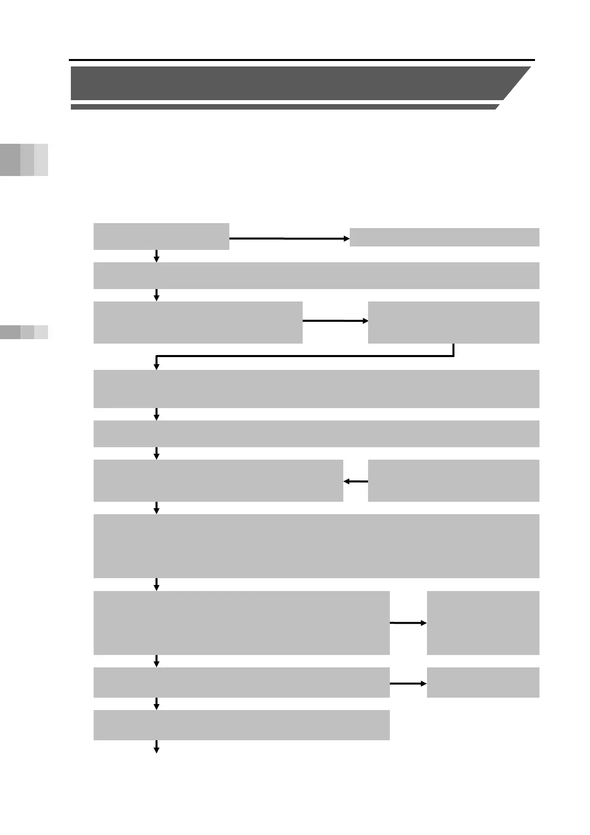
Assembling RCON (connecting the unit)
Connect the units to be used, such as gateway unit, driver unit, EC connection unit and expansion unit.
Install and wire the actuator and controller.
· Is the frame ground (FG) connected?
· Are noise countermeasures provided?
Initial setting (gateway setting) * Gateway parameter configuration tool is used.
Set the unit configuration, number of axes, axis number, operation mode, address (station number), field network communication
speed and the like according to the system. If the number of axes is incorrect, the PC software cannot be connected.
Initial setting (driver unit/EC connection unit /expansion unit setting) * PC software is used.
Set the parameters for each controller.
Checking the package
Are all deliverables present?
Contact IAI or the local IAI distributor.
Communication setting of PLC (master unit)
* Refer to the PLC instruction manual.
Set the PLC node address (station number), communication speed, etc.
·
Are the continuous mode and control sequence
that supports the system incorporated?
(1) Turn on the power of the PLC (master unit).
(2)
When using the SCON expansion unit, turn on the power of the SCON connected to the SCON expansion
unit.
(3) Turn on the power of the RCON.
Confirming that communication is established
·
Make sure that communication is established, with the gateway unit
LED.
·
Make sure that communication is also established on the PLC (master unit).
* Refer to the PLC instruction manual.
Check the cause of the error
through the LEDs and the like
and take appropriate actions. If
the cause is unknown, try setting
again from the beginning.
Checking the safety circuit
Confirm that the stop circuit (drive-source cutoff circuit) operates normally.
Check the circuit.
Communication is established and it is ready for operation.
Check the system operation and make adjustments.

 Loading...


