2.2. Wiring
B2-8
ME0384-4A
Chapter 2 Mounting and Wiring
Shown below is an example for how to wire the power supply to a controller.
Refer to “Specifications Section Chapter 2.5 Connection Diagrams (Page A2-32)” for examples
of wiring for the stop circuit and drive cutoff circuit.
[24V power supply wiring to RCON system]
To supply power to the RCON system, power supply wiring to the RCON gateway unit is
required.
The example below shows the wiring of the RCON gateway unit and the IAI 24 VDC power
supply unit PSA-24.
Items to prepare
RCON system/wiring
To supply power to the controller, mount the power connector and wire each terminal.
Perform
1 to 4 with reference to the figure and connection diagram below.
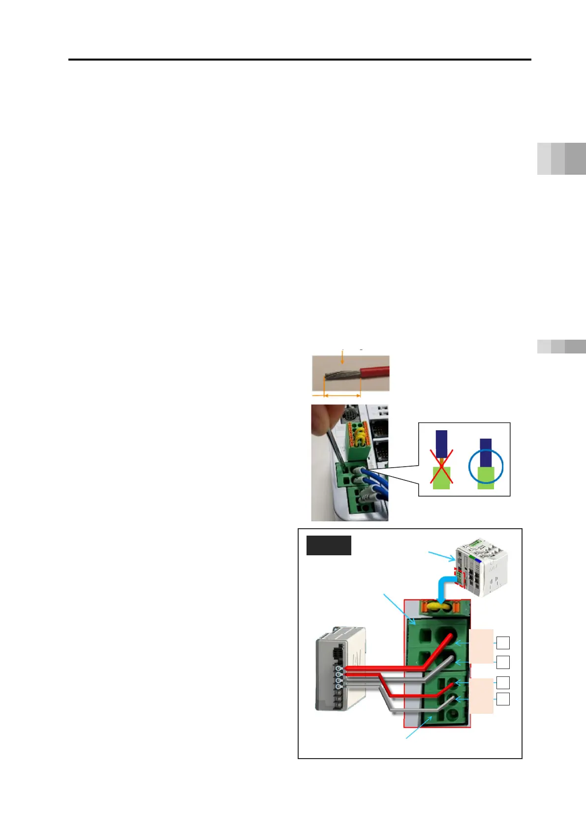
[Wiring method to 24V power connector]
(1) Refer to the next page for each wiring
diameter.
(2) The strip length of the wiring is
· MP: 15 mm
· CP: 10 mm
(3) Insert the wire all the way into the
terminal port while pushing the flathead
screwdriver into the hole next to the
wire insertion port.
(4) Remove the screwdriver.
Connect the "24 V" of MP (motor
power connector) to the +24 V terminal
of the 24 VDC power supply.
Connect the "0 V" of MP (motor power
connector) to the 0 V terminal of the 24
VDC power supply.
Connect the "24 V" of CP (control
power connector) to the +24 V terminal
of the 24 VDC power supply.
Connect the "0 V" of CP (control power
connector) to the 0 V terminal of the 24
VDC power supply.
Gateway unit
24VDC power
supply
24 V
0 V
24 V
0 V
Strip length

 Loading...


