4.4 Address Configuration
B4-49
ME0384-4A
Chapter 4 Network Configuration
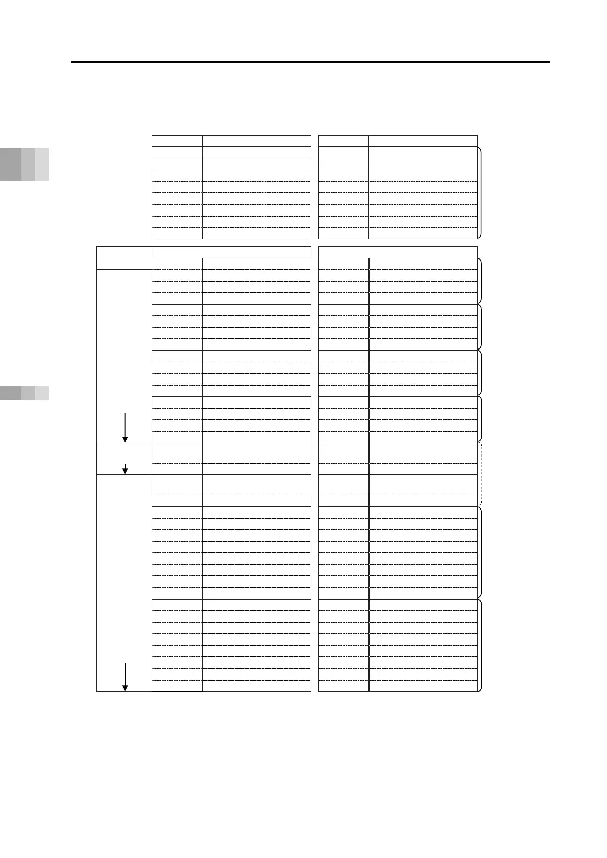
■ CC-Link overall address configuration example (direct numerical control mode + simple direct
mode/positioner 1 mode) shows direct numerical control mode connection for 2 axes and
simple direct or positioner 1 mode connection for 12 axes.
Power supply unit status signal 0
Power supply unit status signal 1
Power supply unit status signal 2
Power supply unit status signal 3
Power supply unit status signal 4
extended
(Axis 0) Specified position data (L)
(Axis 0) Present position data (L)
(Axis 0) Specified position data (H)
(Axis 0) Present position data (H)
(Axis 0) Command position No.
(Axis 0) Completed position No.
(Axis 1) Specified position data (L)
(Axis 1) Present position data (L)
(Axis 1) Specified position data (H)
(Axis 1) Present position data (H)
4 words each
(Axis 1) Command position No.
(Axis 1) Completed position No.
(Axis 2) Specified position data (L)
(Axis 2) Present position data (L)
(Axis 2) Specified position data (H)
(Axis 2) Present position data (H)
4 words each
(Axis 2) Command position No.
(Axis 2) Completed position No.
(Axis 3) Specified position data (L)
(Axis 3) Present position data (L)
(Axis 3) Specified position data (H)
(Axis 3) Present position data (H)
4 words each
(Axis 3) Command position No.
(Axis 3) Completed position No.
32-word
4x multiplier setting 2 stations
・
・
・
・
・
・
・
(Axis 12) Specified position data (L)
(Axis 12) Present position data (L)
(Axis 12) Specified position data (H)
(Axis 12) Present position data (H)
(Axis 12) Specified positioning width (L)
(Axis 12) Present current value (L) *3
(Axis 12) Specified positioning width (H)
(Axis 12) Present current value (H) *3
(Axis 12) Specified speed
(Axis 12) Present speed data
(Axis 12) Specified acceleration/deceleration
(Axis 12) Pushing current limit value
(Axis 13) Specified position data (L)
(Axis 13) Present position data (L)
(Axis 13) Specified position data (H)
(Axis 13) Present position data (H)
(Axis 13) Specified positioning width (L)
(Axis 13) Present current value (L) *3
(Axis 13) Specified positioning width (H)
(Axis 13) Present current value (H) *3
8 words each
(Axis 13) Specified speed
(Axis 13) Present speed data
(Axis 13) Specified acceleration/deceleration
(Axis 13) Pushing current limit value
*1 Extended cyclic settings are performed based on the occupancy information displayed with the
gateway parameter configuration tool.
*2 Operation is also possible with CC-Link Ver.1.10 if extended cyclic 1x multiplier settings (4 stations
occupied) are within the usable range.
*3 The present current value should be the command current value for the stepper motor and be the
feedback current value for the AC servomotor (including AC servomotor connected to SCON-CB).
words each

 Loading...


