EasyManuals Logo

IAI Rcon User Manual

IAI Rcon
838 pages
To Next Page IconTo Next Page
To Previous Page IconTo Previous Page
Page #471 background imageLoading...
Page #471 background image
4.4 Address Configuration
B4-50
ME0384-4A
Chapter 4 Network Configuration
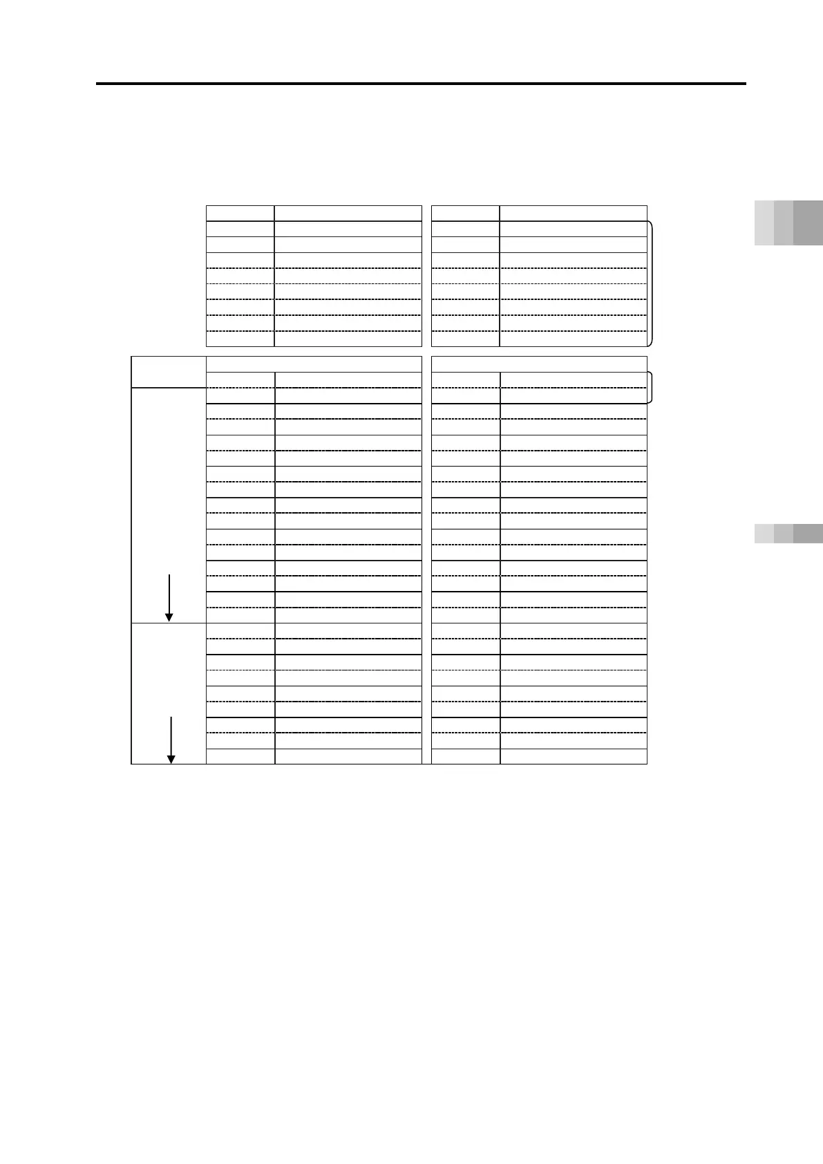
Startup Section
CC-Link overall address configuration example (positioner 2 mode + EC connection unit)
It is an example of having 12 axes in Positioner 2 Mode and one unit of the EC connection unit
getting connected.
PLC output RCON
RCON PLC input
Output register
High byte
Low byte
Input register
High byte
Low byte
RY0F ~ 00
Gateway control signal 0
RX0F ~ 00
Gateway status signal 0
RY1F ~ 10
Gateway control signal 1
RX1F ~ 10
Gateway status signal 1
RY2F ~ 20
(Not available)
RX2F ~ 20
Power supply unit status signal 0
RY3F ~ 30
(Not available)
RX3F ~ 30
Power supply unit status signal 1
8 words each
RY4F ~ 40
(Not available)
RX4F ~ 40
Power supply unit status signal 2
Fixed region
RY5F ~ 50
(Not available)
RX5F ~ 50
Power supply unit status signal 3
RY6F ~ 60
(Not available)
RX6F ~ 60
Power supply unit status signal 4
*1
RY7F ~ 70
(Not available)
RX7F ~ 70
(Not available)
PLC master
extended
cyclic settings
Output register
Input register
Rw 00H
(Axis 0) Command position No.
Rr 00H
(Axis 0) Completed position No.
2 words each
Rw 01H
(Axis 0) Control signal
Rr 01H
(Axis 0) Status signal
Rw 02H
(Axis 1) Command position No.
Rr 02H
(Axis 1) Completed position No.
Rw 03H
(Axis 1) Control signal
Rr 03H
(Axis 1) Status signal
Rw 04H
(Axis 2) Command position No.
Rr 04H
(Axis 2) Completed position No.
Rw 05H
(Axis 2) Control signal
Rr 05H
(Axis 2) Status signal
Rw 06H
(Axis 3) Command position No.
Rr 06H
(Axis 3) Completed position No.
Rw 07H
(Axis 3) Control signal
Rr 07H
(Axis 3) Status signal
Rw 08H
(Axis 4) Command position No.
Rr 08H
(Axis 4) Completed position No.
Rw 09H
(Axis 4) Control signal
Rr 09H
(Axis 4) Status signal
16-word
Rw 0AH
(Axis 5) Command position No.
Rr 0AH
(Axis 5) Completed position No.
Rw 0BH
(Axis 5) Control signal
Rr 0BH
(Axis 5) Status signal
1x multiplier setting 4
Rw 0CH
(Axis 6) Command position No.
Rr 0CH
(Axis 6) Completed position No.
*2
Rw 0DH
(Axis 6) Control signal
Rr 0DH
(Axis 6) Status signal
Rw 0EH
(Axis 7) Command position No.
Rr 0EH
(Axis 7) Completed position No.
Rw 0FH
(Axis 7) Control signal
Rr 0FH
(Axis 7) Status signal
RWw 10H
(Axis 8) Command position No.
Rr 10H
(Axis 8) Completed position No.
RWw 11H
(Axis 8) Control signal
Rr 11H
(Axis 8) Status signal
RWw 12H
(Axis 9) Command position No.
Rr 12H
(Axis 9) Completed position No.
32-word
RWw 13H
(Axis 9) Control signal
Rr 13H
(Axis 9) Status signal
RWw 14H
(Axis 10) Command position No.
Rr 14H
(Axis 10) Completed position No.
4x multiplier setting 2
RWw 15H
(Axis 10) Control signal
Rr 15H
(Axis 10) Status signal
RWw 16H
(Axis 11) Command position No.
Rr 16H
(Axis 11) Completed position No.
RWw 17H
(Axis 11) Control signal
Rr 17H
(Axis 11) Status signal
RWw 18H
(Axis 12 ~ Axis 15) Control signal
Rr 18H
(Axis 12 ~ Axis 15) Status signal
1 word *3
*1 Extended cyclic settings are performed based on the occupancy information displayed with
the gateway parameter configuration tool.
*2 Operation is also possible with CC-Link Ver.1.10 if extended cyclic 1x multiplier settings (4
stations occupied) are within the usable range.
*3 The EC connection unit occupies domains and axis numbers for four axes (one word) even if
not all of four axes are connected.
The axes numbers for the EC connection unit should be assigned from the back of those in
the driver unit (RCON-PC/AC/DC/PCF/SC) and the SCON extension unit.

Table of Contents

Questions and Answers:

Question and Answer IconNeed help?

Do you have a question about the IAI Rcon and is the answer not in the manual?

IAI Rcon Specifications

General IconGeneral
BrandIAI
ModelRcon
CategoryController
LanguageEnglish

Related product manuals