2.5 Connection Diagrams
A2-35
ME0384-4A
Chapter 2 System Configuration and Specifications
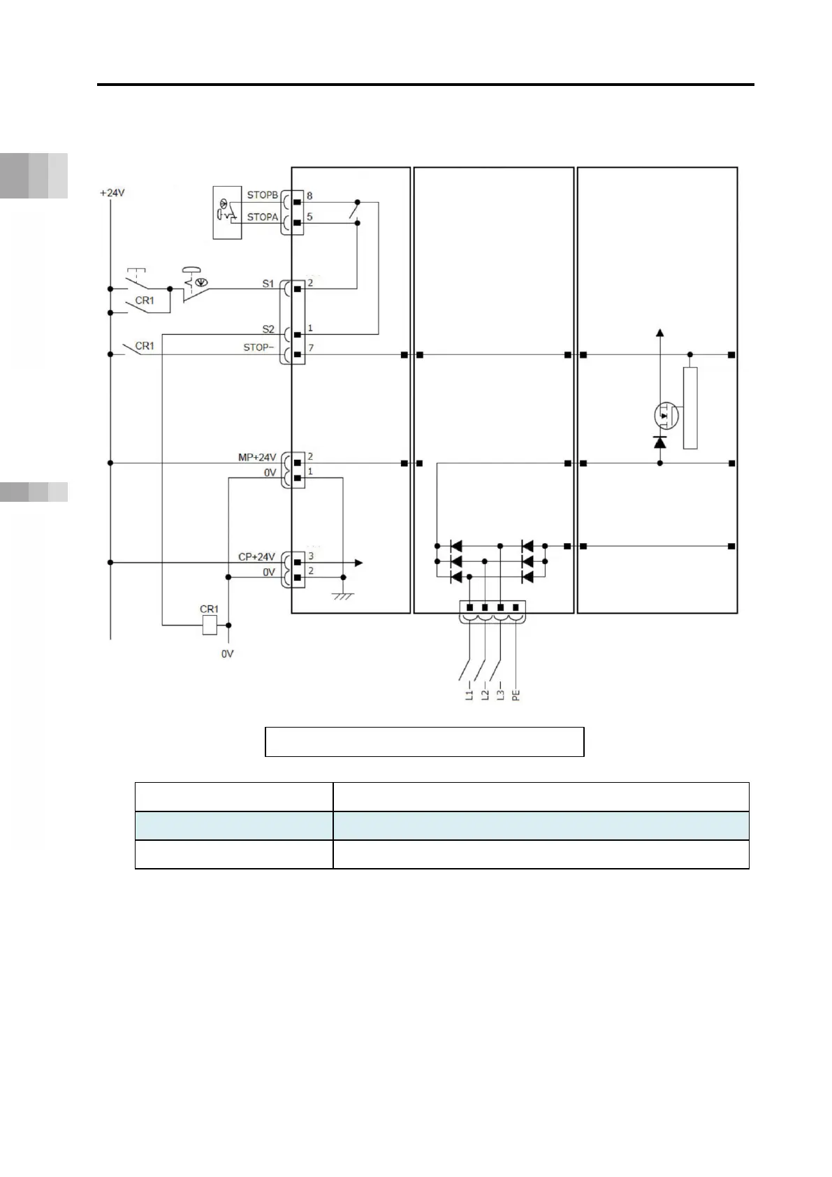
[Example of Circuit (for 200V System)]
Item Specifications
STOP-input 24 VDC ±10% / 10mA or less
S1 and S2 input 24 VDC ±10% / 0.1A or less
Note 1: RCON-GW : If nothing is connected to the SIO connector, S1 and S2 will be short-
circuited in the controller.
RCON-GWG : If nothing is connected to the SIO connector, S1 and S2 will not be
short-circuited in the controller.
To short-circuit, connect the supplied dummy plug DP-5 to the SIO
connector.
Wiring diagram: Stop and drive-source cutoff
High-
Emergency
Stop Reset
Switch
Motor Power
Supply Connector
for 24V Driver
Teaching pendant
Stop switch
24V Power Supply Unit
r
Motor Power
Supply Connector
for 200V Driver

 Loading...


