2.5 Connection Diagrams
A2-36
ME0384-4A
Chapter 2 System Configuration and Specifications
Note : • When externally shutting off the motor drive source to comply with the safety category
or the like, connect a contact such as a relay to the wiring between the MPI* and MPO*
terminals.
• The rating of the STOP-signal to be turned ON/OFF with the contact CR1 is 24 VDC / 10
mA or less.
• The CR1 coil current must be 0.1 A or less.
• When supplying power by turning ON/OFF 24 VDC, leave 0 V connected and supply/cut
off +24 V.
• Consider the wire diameter and length for the drive cutoff connector wiring so the
voltage would not drop.
• There may be a case that an alarm gets generated due to the voltage drop supplied to
the controller caused by inappropriate wire diameter and length. In such a case, adjust
the output voltage of the power supply to secure 24V for the voltage supplied to the
controller.
Warning
● The stop switch on a teaching pendant can stop all the actuators connected to RCON,
however, it cannot stop the system.
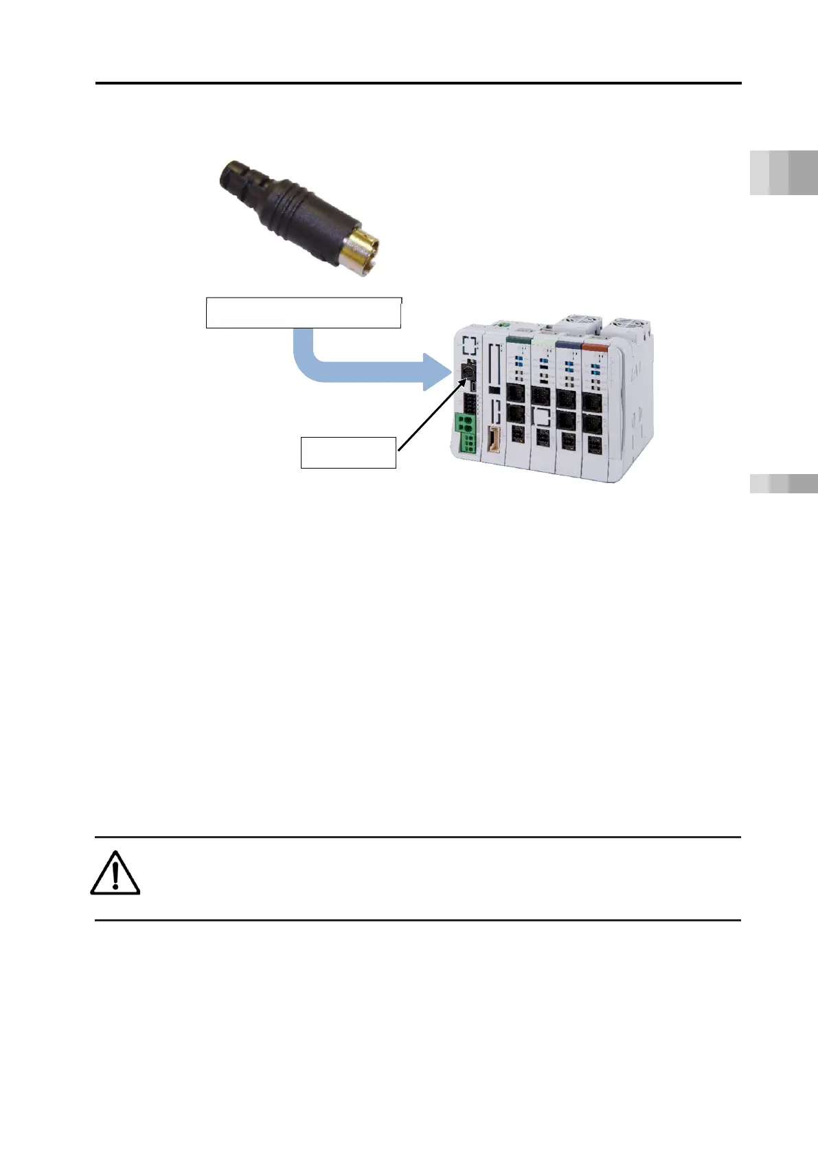
Dummy plug (model: DP-5)
SIO connector

 Loading...


