2.5 Connection Diagrams
A2-38
ME0384-4A
Chapter 2 System Configuration and Specifications
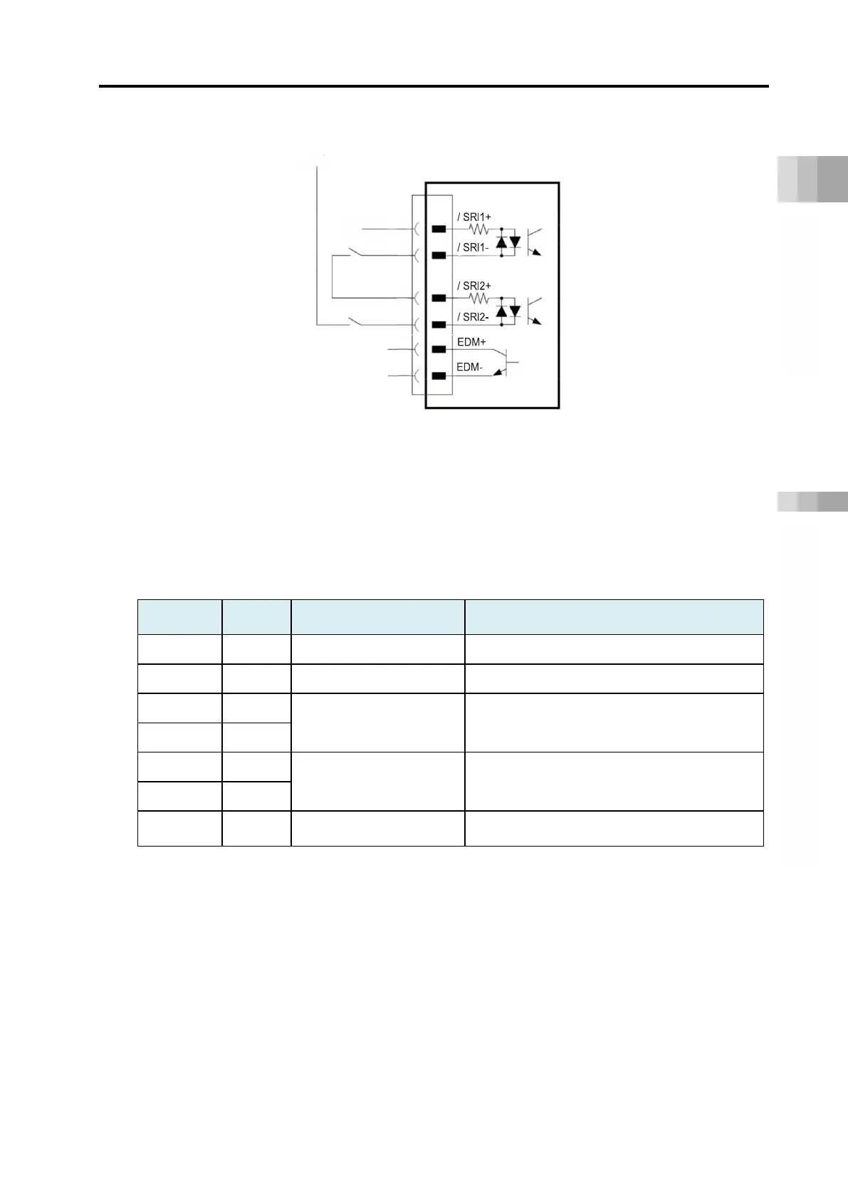
[Example for Wiring]
By wiring a shown in the diagram above, the driver features can be stopped when the switch is
turned off.
Note 1: Have the 0V in common with the 24V power supply of the gateway unit.
[Signals on Driver Stop Connector]
Connector Name on Driver unit Side: 2013595-1 (Tyco Electronics)
Pin No.
Name Explanation
1 NC - Do not apply
2 NC - Do not apply
3 /SRI1-
Stop Input Signal 1
Stop input signal should be input.
On: DRV STOP released
Off: In DRV STOP (Motor current cutoff)
4 /SRI1+
5 /SRI2-
Stop Input Signal 2
Stop input signal should be input.
On: DRV STOP released
Off: In DRV STOP (Motor current cutoff)
6 /SRI2+
7 EDM-
External Device Monitor
Output Signal
It is an output signal to show the stop feature
is in operation with no failure.
 Loading...


