EasyManua.ls Logo

IAI Rcon - Page 97

IAI Rcon
838 pages
To Next Page IconTo Next Page
To Previous Page IconTo Previous Page
Loading...
2.5 Connection Diagrams
A2-52
ME0384-4A
Chapter 2 System Configuration and Specifications
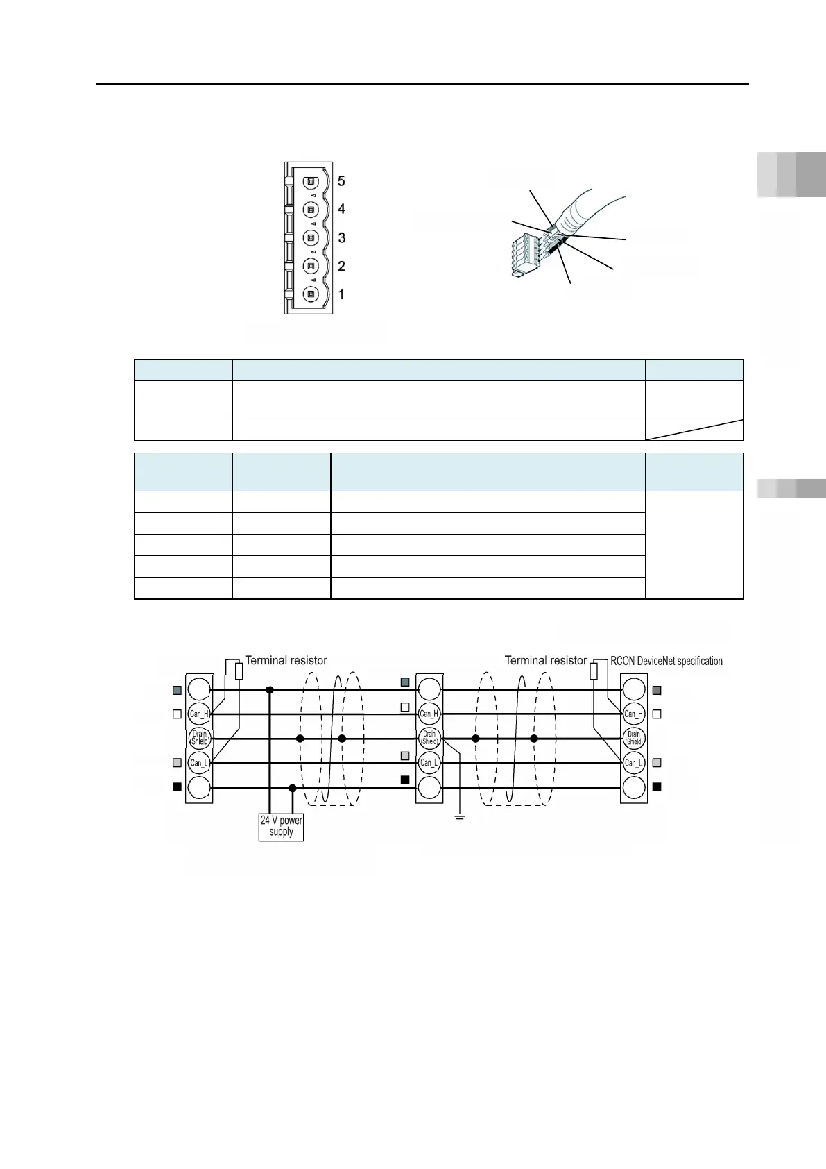
Specifications Section
[DeviceNet]
Connector name
DeviceNet cable connector
Remarks
Cable side MSTB2.5/5-STF-5.08 AU M (Phoenix Contact)
Standard
accessories
Controller side
MSTBA2.5/5-GF-5.08 AU (Phoenix Contact)
Pin No.
Signal name
(color scheme)
Description
Compatible
wire diameter
1
V- (black)
Power supply cable - side
DeviceNet
dedicated
cable
2
CAN L (blue)
Signal data Low side
3
Digital ground
4
CAN H (white)
Signal data High side
5
V+ (red)
Power supply cable + side
Controller side
Connector top view
Shield
Blue (CAN L)
Black (V-)
White (CAN H)
Red (V+)
Master unit
Slave device
The communication power must be
supplied from the outside.
Grounding resistance: 100 Ω or less
(
Class D grounding construction)
121Ω
121Ω
V+
V-
V+
V-
V+
V-
Red
White
Black
Blue
Red
White
Black
Blue
Red
White
Black
Blue
At the terminal, a terminal
resistor needs to be connected.

Table of Contents

Related product manuals