6-52 ELECTRICAL SYSTEM / BILGE PUMP
ICON A5 / MAINTENANCE MANUAL CHANGE C2
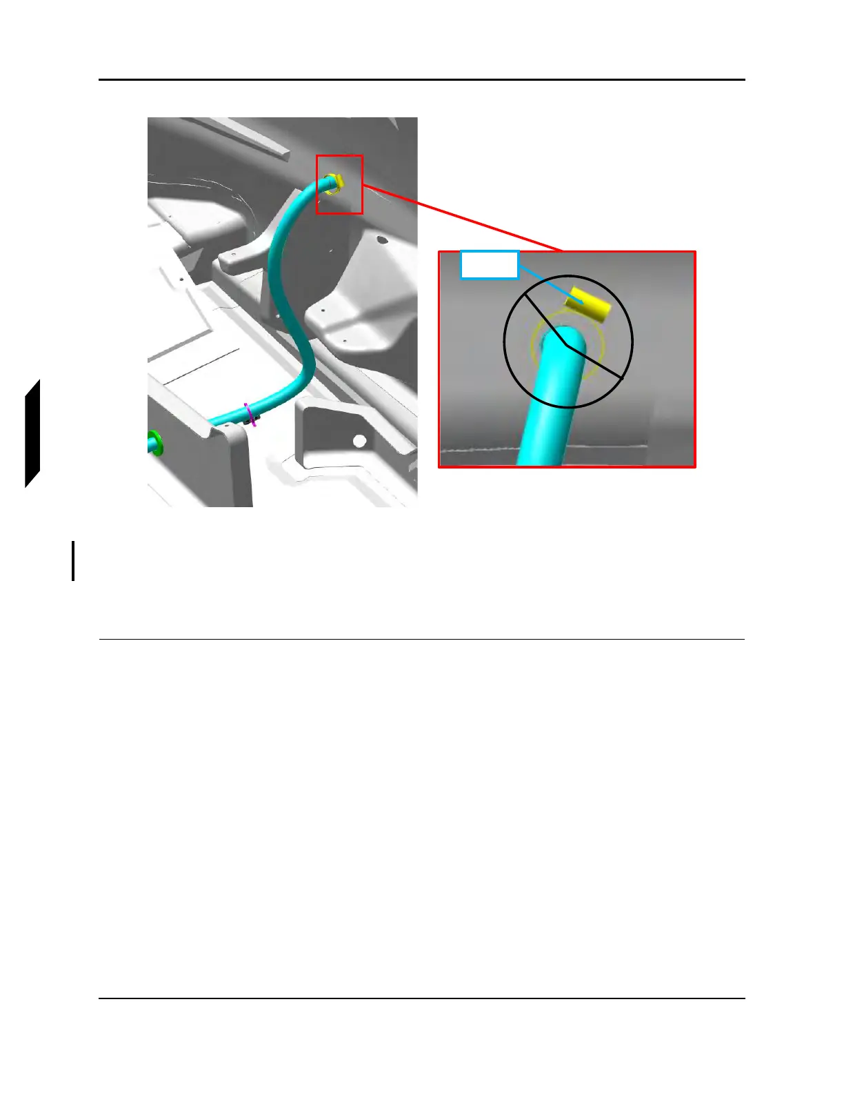
FIGURE 6-12
CLAMP ORIENTATION
6. Connect D9009J connector on bilge pump to D9009P connector on main wire harness.
7. Test that the bilge pump operates normally.
8. Install the fuel tank. (See “Install Fuel Tank (MY18+)” on page 10-19.)
VERIFICATION METHOD:
The procedure is complete when the fuel tank is installed.