8-14 EQUIPMENT AND FURNISHINGS / EQUIPMENT AND FURNISHINGS GENERAL MAINTENANCE
ICON A5 / MAINTENANCE MANUAL CHANGE C1
LSA-RM
Task Specific Training Required
No
Special Tools
No
Parts Required
None
Aircraft System and Number
05—Equipment and Furnishing
Consumables
LOCTITE
®
243™
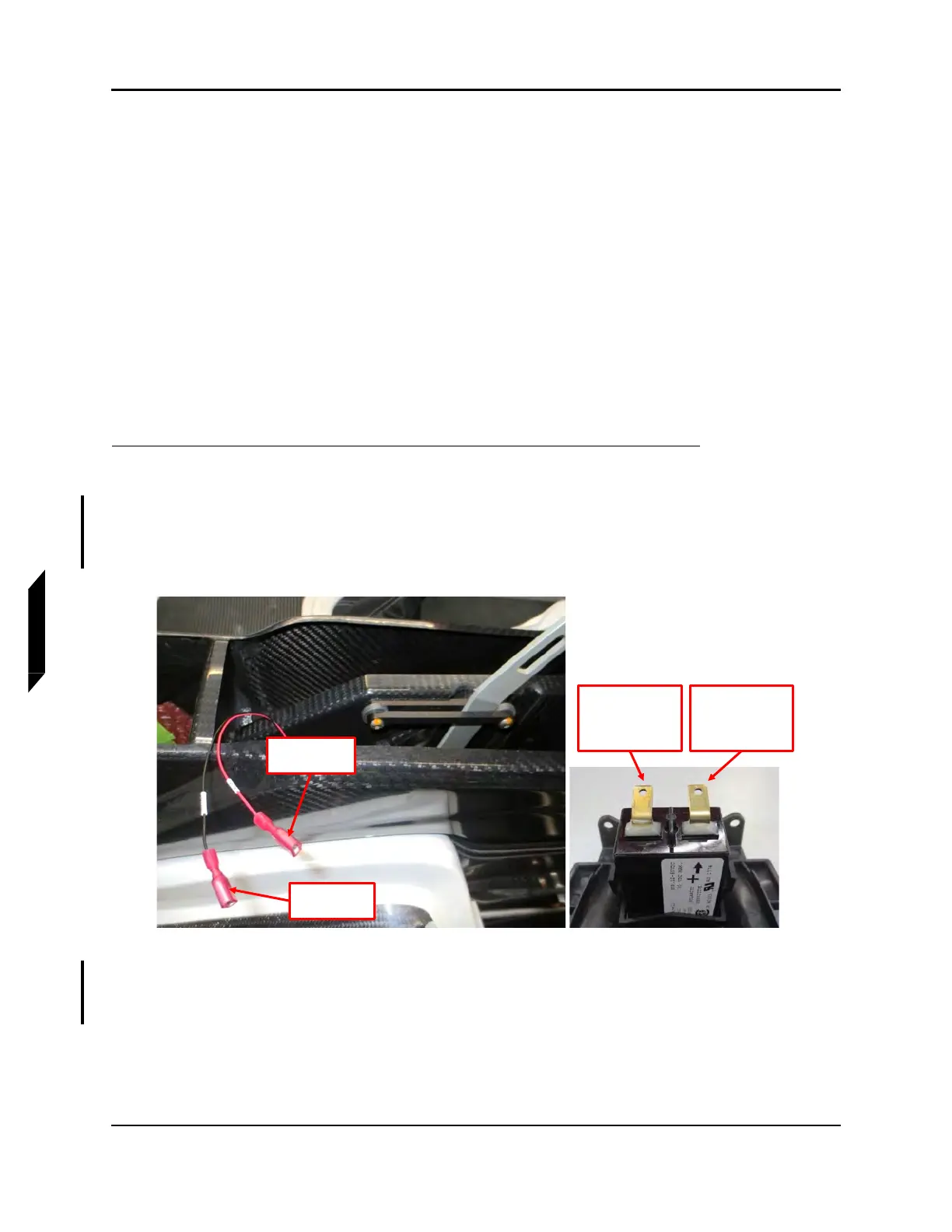
1. Connect electrical connections as follows, refer to Figure 8-10:
a. Connect T9114 terminal on fuselage wiring harness to the positive terminal (+) on hour
meter.
b. Connect T9105 terminal on fuselage wiring harness to the negative terminal (-) on hour
meter.
FIGURE 8-10
THROTTLE BEZEL ELECTRICAL CONNECTIONS
2. Install throttle bezel. Slide bezel tabs under radio stack bezel and push bezel into place. See
Figure 8-9.
T9114
Terminal
T9105
Terminal
POSITIVE
TERMINAL
CONNECTS TO
T9114
NEGATIVE
TERMINAL
CONNECTS TO
T9105