FLIGHT CONTROLS / FLIGHT CONTROL SYSTEM GENERAL MAINTENANCE 9-7
CHANGE C3 ICON A5 / MAINTENANCE MANUAL
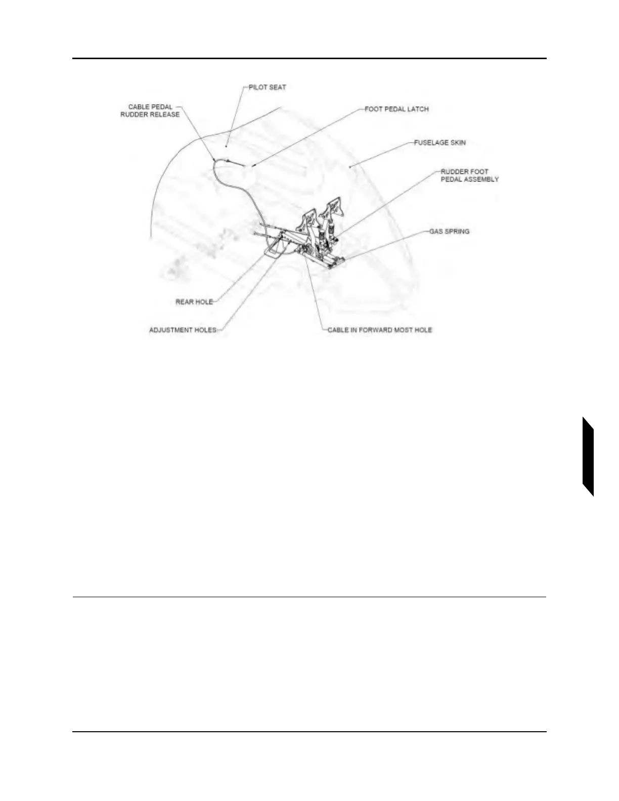
FIGURE 9-3
RUDDER PEDAL LATCH LOCATIONS UNDER PILOT AND CO-PILOT SEATS.
3. Ensure pedals completely move aft via a gas strut upon pulling the lever.
4. Release lever.
5. Push on pedals to obtain positive engagement.
Positive engagement is reached when pedals cannot be moved while applying load on heel strike.
6. Ensure the rudder cables going through the floor are free to operate and the pedals move freely.
7. Pull the lever again and unlock the locking mechanism.
8. Push with heel on heel strike in between the pedals on floor.
9. Confirm pedal assembly moves forward freely with ~30 lbs of force.
10. Release handle and load on heal strike and ensure positive engagement.
11. Ensure the rudder cables going through the floor are free to operate and the pedals move freely.
12. Replace the floorboard immediately in front of the pilot seat. (See “Cockpit Floor Board Installa-
tion” on page 3-47.)
13. Repeat this process for the co-pilot seat.
VERIFICATION METHOD:
Verify that results are within acceptable limits.