9-98 FLIGHT CONTROLS / YAW CONTROLS
ICON A5 / MAINTENANCE MANUAL CHANGE C3
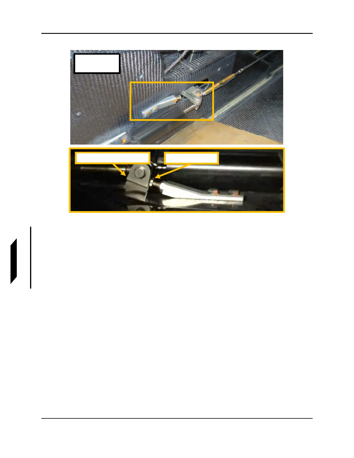
FIGURE 9-63
SECONDARY STOP ADJUSTMENT
19. Remove all rig pins from the Yaw System:
a. 2X rig pins from Yaw Torque Tubes
b. Rig pin from FWD Yaw Bellcrank
c. Rig pin from AFT Water Rudder Bellcrank
20. Verify that Yaw System components do not contact surrounding carbon surfaces or components
during operation.
21. Verify that the rudder neutral position is still within the limits specified. Adjust if necessary.
Torque push tube jam nuts to 40 in-lbs. Torque through bolts that secure the push tube to 26
in-lbs.
22. With the aid of another person, check the rudder maximum travel limits. Have a helper push each
rudder pedal against the stop (stop contacts at water rudder bellcrank should be heard). While
holding very light (1-2 lb
f
) pressure towards neutral on the rudder trailing edge to remove play.
23. Adjust primary stops to ensure rudder maximum travel limits are set as specified. See Figure
9-64.
a. Trailing Edge Left: 11°+/-1°
b. Trailing Edge Right: 14°+/-1°
Forward Yaw Bellcrank
Secondary Stop
LH SHOWN
RH OPPOSITE