FLIGHT CONTROLS / YAW CONTROLS 9-99
CHANGE C3 ICON A5 / MAINTENANCE MANUAL
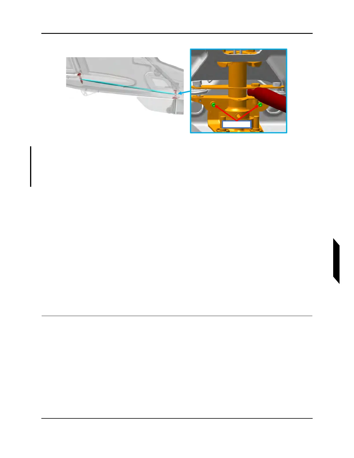
FIGURE 9-64
PRIMARY STOP LOCATIONS
24. With the aid of another person, adjust the secondary stops, torque to 12-15 in-lbs. Do not exceed
25 in-lbs. Depress the RH pedal until the primary stop is contacted. Adjust the gap between the
secondary stop and bellcrank to 0.032-0.036 in. See Figure 9-63.
25. Repeat step 17 for the LH pedal.
26. Install AFT Tail Access Panel, Water Rudder Access Panel, and AFT Bulkhead Baggage Panel.
(See “Removal and Installation of Inspection Panels and Fairings” on page 3-34.)(See “Baggage
Floor Installation” on page 3-42.)
27. Install left hand and right hand forward and Main Cockpit Floor Boards. (See “Cockpit Floor
Board Installation” on page 3-47.)
28. Install Seat Back and Seat Pan. (See “Seat Back Installation” on page 3-51.)(See “Seat Pan Instal-
lation” on page 3-53.)
29. Install Baggage Floor Boards. (See “Baggage Floor Installation” on page 3-42.)
30. Install Seatbelt Reel Cover, left hand and right hand baggage sidewalls, and Baggage Headliner.
(See “Seat Belt Inertia Reel Installation” on page 3-40.)(See “Baggage Sidewall Panel Installa-
tion” on page 3-45.)(See “Headliner Installation” on page 3-38.)
31. If fuel tank was removed, install fuel tank. (See “Install Fuel Bladder (MY17 Only)” on page 10-12.)
(See “Install Fuel Tank (MY18+)” on page 10-19.)
32. Install Center Console Bucket and Throttle Bezel. (See “Center Console Bucket Installation” on
page 8-8.)(See “Throttle Handle and Bezel Installation” on page 8-13.)
VERIFICATION METHOD:
Conduct the Check Rudder Rigging procedure (See “Inspect Yaw Rigging” on page 9-85.) to verify
proper rigging.