FLIGHT CONTROLS / YAW CONTROLS 9-105
CHANGE C3 ICON A5 / MAINTENANCE MANUAL
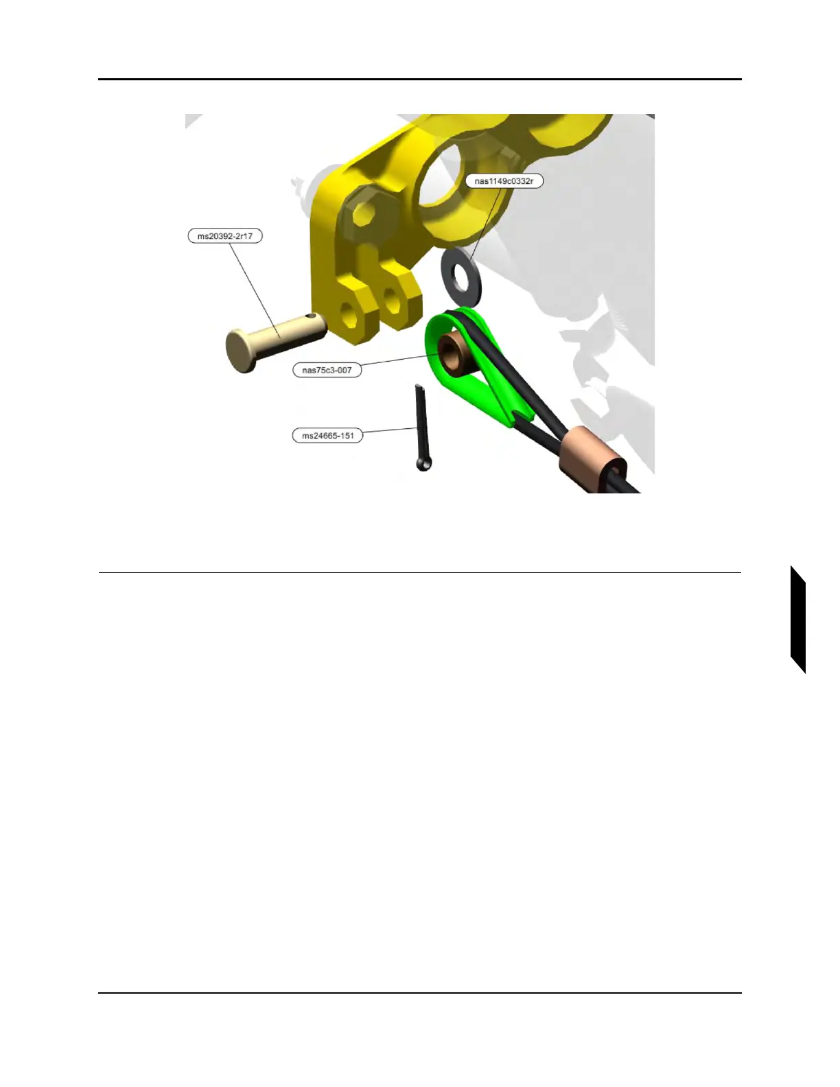
FIGURE 9-66
RUDDER PEDAL FWD MOUNT CABLE INSTALLATION
9. Install the floorboard panels to the aircraft by locating them in position and pressing downward.
VERIFICATION METHOD:
Perform the rudder pedal inspection procedure. (See “Inspect Rudder Pedal Rigging” on page 9-83.)
Confirm correct rigging for entire yaw control system by performing the water rudder inspection
procedure and the rudder inspection procedure.(See “Inspect Yaw Rigging” on page 9-85.)(See
“Check Water Rudder Rigging” on page 11-12.)
Confirm that at the pedal movement maximum travel the primary stops in the horizontal tail are met
first. The secondary stops, under the center console, should be met after cable tension has been
applied.
RELATED INFORMATION:
"Inspect Rudder Pedal Rigging" on page 9-83
"Inspect Rudder Pedal Adjustment Mechanism" on page 9-5
"Adjust Rudder Pedal Rigging" on page 9-101
"Re-Rigging Rudder Pedals" on page 9-103
"Removal and Installation of Inspection Panels and Fairings" on page 3-34
"Inspect Yaw Rigging" on page 9-85
"Check Water Rudder Rigging" on page 11-12