INSTRUMENTS (AND AVIONICS) / INSTRUMENTS AND AVIONICS GENERAL MAINTENANCE 13-17
CHANGE C2 ICON A5 / MAINTENANCE MANUAL
1. Remove the four light control knobs from the overhead console by pulling each down and off
their D-shafts.
2. Remove the overhead console bezel by pulling down on its forward edge, disengaging two spring
clips. Disengage the two indexing tabs at the aft edge of the bezel, then remove the bezel.
3. Disconnect the D9078P and D9079J wire harness connectors and the ELT remote cable
connector (telephone-type) from the overhead console.
4. Detach the overhead console by using a T15 Torx driver to remove the six 96710A318 pan-head
screws that secure it (the screws thread into nutplates).
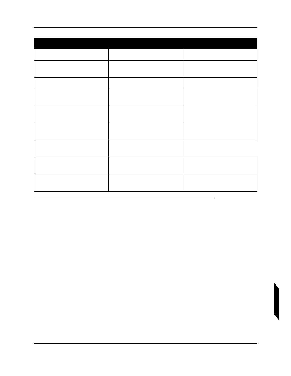
5. Place the overhead console on a clean work surface and replace any damaged or faulty compo-
nent indicated in the figure and table below.
6. Use the graphic and associated parts list table to select the appropriate replacement compo-
nents and then remove and replace the components.
7. After component replacement, install the overhead console with the six 96710A318 pan-head
screws. Watch out for pinch points at the screw bosses to avoid damaging wiring. Torque each
screw to 13 in-lb
f
.
8. Connect the D9078P and D9079J wire harness connectors and the ELT phone connector.
013 ICA010373 Driver Module, OHC
014 ICA010374 Illuminator Light, OHC, Instr
PNL, Red
015 ICA010376 Illuminator Light, OHC, White
021 96817A890 Screw, Torx Panhead, 18-8,
M2.5X0.95
022 TY24MX Cable-tie, Nylon 6-6, 30lb,
5.50, TY-RAP
023 ICA010401 Potentiometer, 10K, Instrument
Panel Lighting
024 ICA010403 Potentiometer, 10K, OHC
Lighting
025 ICA010404 Potentiometer, 10K, Center
Stack Lighting
031 ICA010375 Illuminator Light, OHC, Ctr Stk,
Red
Find Number Part Number Name