13-34 INSTRUMENTS (AND AVIONICS) / INSTRUMENTS AND AVIONICS GENERAL MAINTENANCE
ICON A5 / MAINTENANCE MANUAL CHANGE C2
1. Access the instruments and switches listed in the following table. (See “GPS Mount and Radio
Stack Bezel Removal” on page 8-15.) The following table details the connections for instruments
located in the Center Console Bucket.
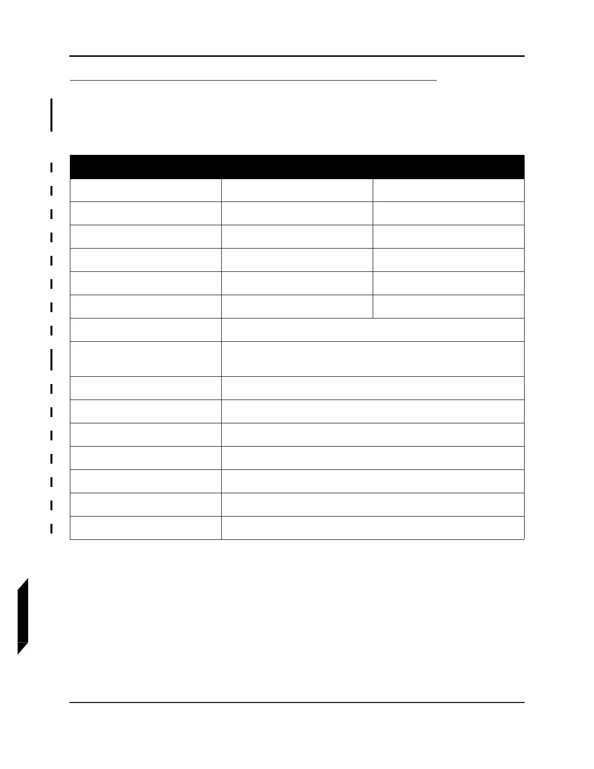
Tab l e 1 3 -1 : Center Stack Wire Instruments Wiring
Instrument/Switch Connection From Connection To
Trim Indicator D9046J D9046P
Flap Switch D9061J D9061P
Landing Gear Switch D9094J D9094P
Heat Control D9084J D9084P
Water Rudder Switch D9060P D9060J
Water Rudder LED D9054J D9054P
VHF Radio Control Unit D9058
Transponder Radio Control
Unit
D9068
STROBE Light Switch T9307 & T9301
NAV Light Switch T9308 & T9300
TAXI Light Switch T9305 & T9303
LAND Light Switch T9304 & T9302
Bilge Pump Switch T9306 & T9309
Bilge Pump LED D9055J & D9055P
Landing Gear Indicator D9045P