14-62 LANDING GEAR / NOSE LANDING GEAR
ICON A5 / MAINTENANCE MANUAL CHANGE C2
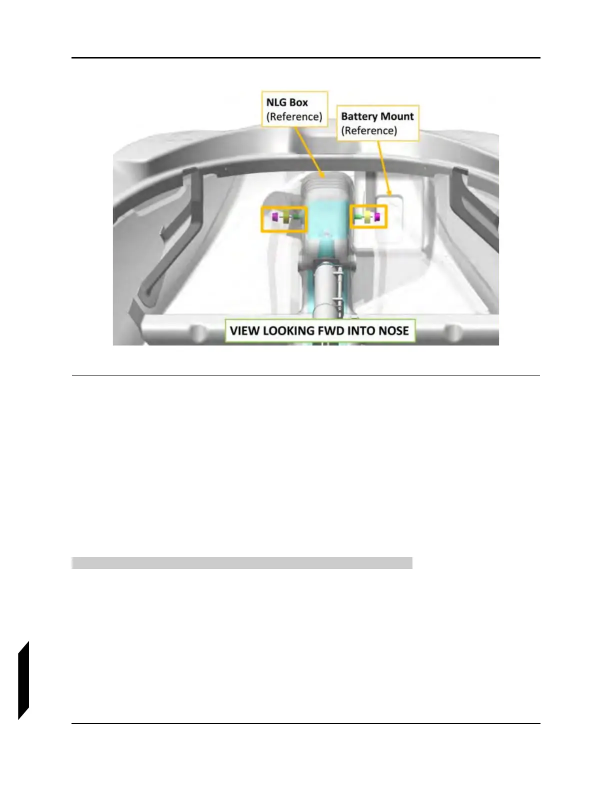
NOTE: There is a bushing in the bearing on each side of the box.
8. Remove the NLG leg.
VERIFICATION METHOD:
The task is completed when the nose landing gear leg has been removed.
RELATED INFORMATION:
"Right Instrument Panel Top Panel Removal" on page 8-17
"Left Instrument Panel Top Panel Removal" on page 8-19
"Battery Removal and Installation" on page 6-37
14.7.2.4 Nose Landing Gear (NLG) Leg Assembly Installation
Use the following procedure to install the nose landing gear leg assembly.
TASK INFORMATION:
Type of Maintenance
Line
Level of Certification
LSA-RM
Task Specific Training Required
No