Design Guide 117
Intel
®
82870P2 (P64H2)
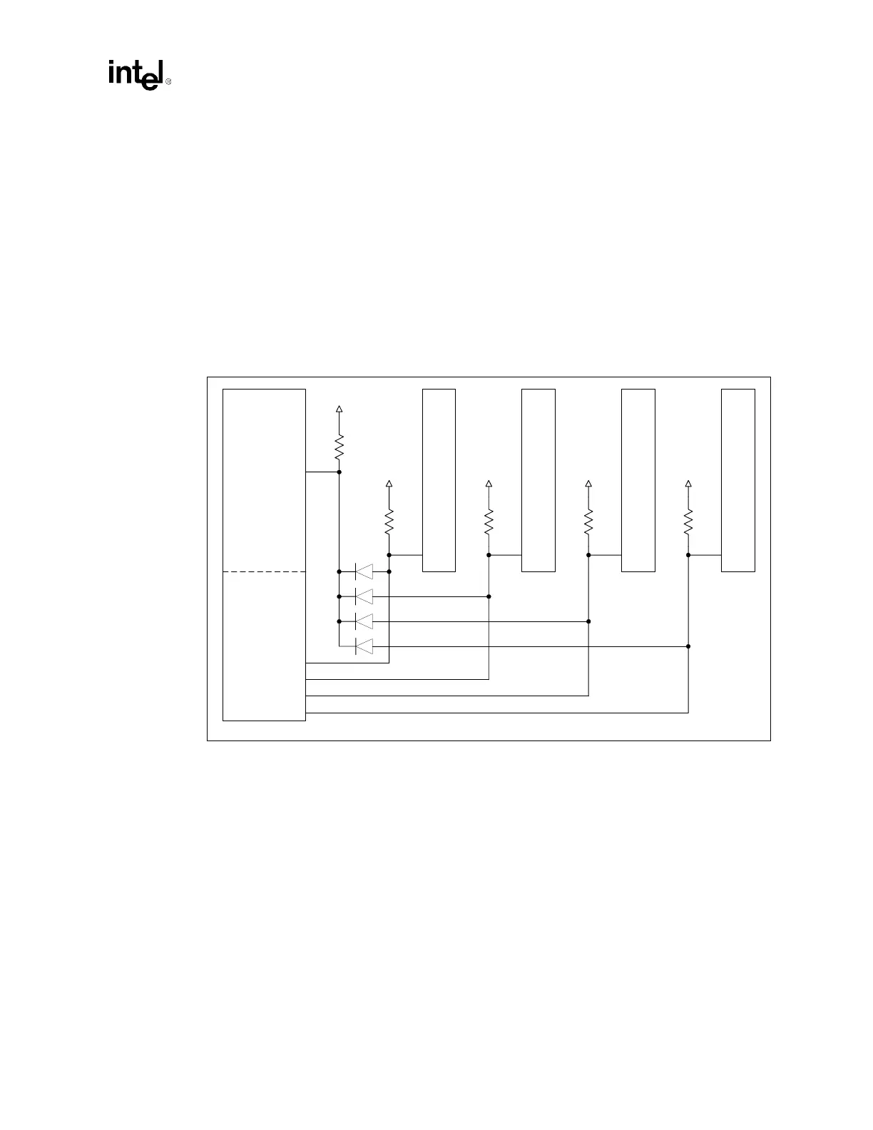
M66EN Diode Solution
Another possible solution is to use diodes to isolate the individual slots from one another while still
allowing the P64H2 to drive the M66EN signals to ground. The P64H2 PCI interface PxM66EN
signal should be pulled to 3.3 V through a 100
kΩ ± 5% resistor. This signal would then be
connected to the individual slots through a reverse biased diode (one diode per slot). The PCI slots
should also be pulled up individually to 3.3 V through a resistor of value such that the equivalent of
all the resistances on the M66EN bus is approximately 5
kΩ (the PCI recommended value). This
circuit will allow the P64H2 to pull the slots’ M66EN to ground during initial power-up. During
normal operation, each of the slots’ M66EN signals will be isolated from one another allowing for
polling of the Hot Plug HxM66EN input for slot capability. Figure 8-18 shows the diode solution
implemented in Serial Mode, where “Slot x M66EN” is a serialized input to the Hot Plug
Controller.
.
NOTE: All PCI signals, muxed or not, must follow PCI Specification 2.2 pull-up requirements.
Figure 8-18. M66EN Diode Solution
Slot
4
Slot
3
Slot
2
Slot
1
20 kΩ
3.3V
20 kΩ
3.3V
20 kΩ
3.3V
20 kΩ
3.3V
100 kΩ
3.3V
M66EN M66EN M66ENM66EN
Slot 3 M66EN
Slot 4 M66EN
Slot 2 M66EN
Slot 1 M66EN
PxM66EN
P64H2 PCI
Interface
P64H2 Hot
Plug Interface