Design Guide 131
I/O Controller Hub
9.6.3 RTC Layout Considerations
Since the RTC circuit is very sensitive and requires high accurate oscillation, reasonable care must
be taken during layout and routing of the RTC circuit. Some recommendations are:
• Reduce trace capacitance by minimizing the RTC trace length. ICH3-S requires a trace length
less than 1 inch on each branch (from crystal's terminal to RTCXn ball). Route the RTC circuit
short to simplify the trace length measurement and increase accuracy when calculating trace
capacitances. Trace capacitance depends on the trace width and dielectric constant of the
board's material. On FR-4, a 5-mil trace has approximately 2 pF per inch.
• Reduce trace signal coupling by avoiding routing of adjacent PCI signals close to RTCX1,
RTCX2, and VBIAS.
• A ground guard plane is highly recommended.
9.6.4 RTC External Battery Connection
The RTC requires an external battery connection to maintain its functionality and its RAM while
the ICH3-S is not powered by the system.
Example batteries are: Duracell* 2032, 2025, or 2016 (or equivalent), which can give many years
of operation.
Batteries are rated by storage capacity. The battery life can be calculated by dividing the capacity
by the average current required. For example, if the battery storage capacity is 170 mAh (assumed
usable), and the average current required is 3 µA, the battery life will be at least:
170,000 µAh / 3 µA = 56,666 h = 6.4 years
The voltage of the battery can affect the RTC accuracy. In general, when the battery voltage
decays, the RTC accuracy also decreases. The battery voltage of the RTC must be greater than 2 V
at all times to ensure the accuracy of the RTC clock.
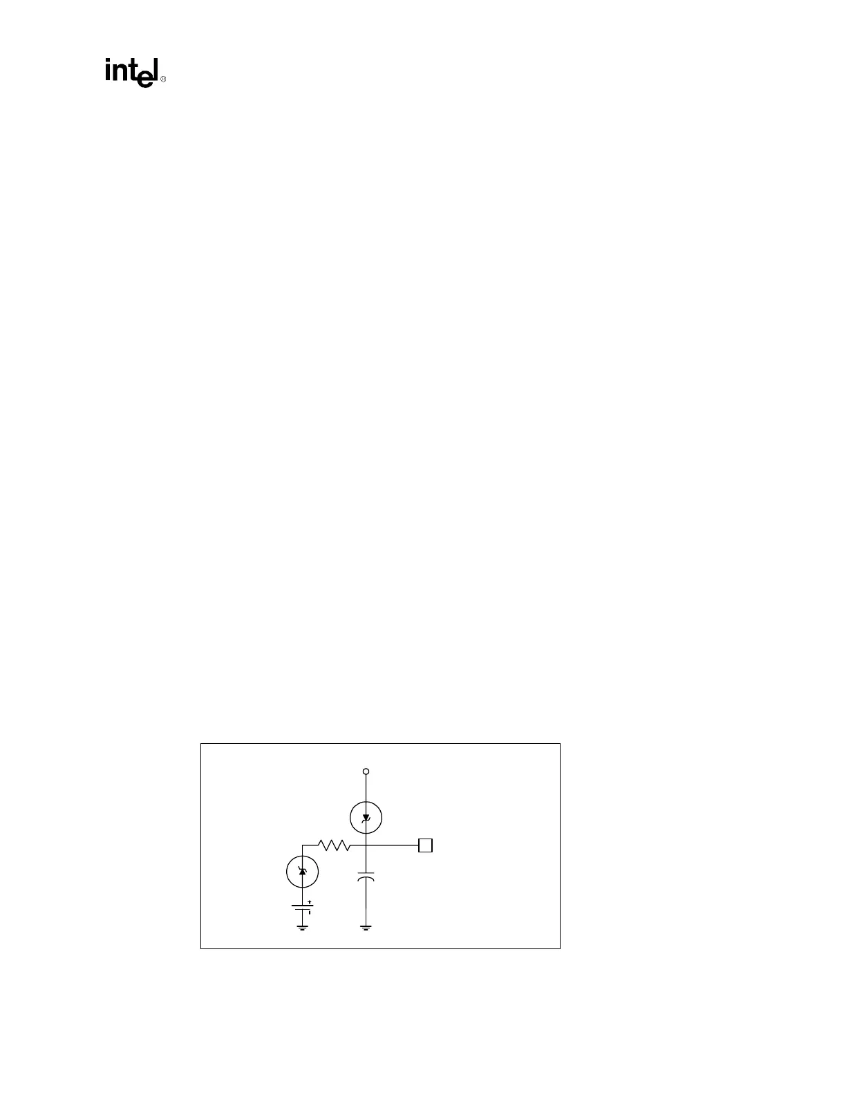
Connect the battery to the ICH3-S via an isolation Schottky diode circuit. The Schottky diode
circuit allows the ICH3-S RTC-well to be powered by the battery when the system power is not
available, and by the system power when it is available. To do this, the diodes are set to be reverse
biased when the system power is not available. Figure 9-12 is an example of a diode circuit.
As noted, a standby power supply should be used in a server system to provide continuous power to
the RTC when available to significantly increase the RTC battery life.
Figure 9-12. A Diode Circuit to Connect RTC External Battery
VCC_3.3SBY
VccRTC
1.0 µF
1 kΩ