Design Guide 211
Layout Checklist
Layout Checklist 14
14.1 Processor Checklist
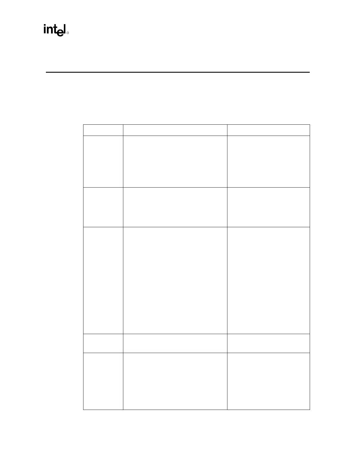
Table 14-1. Processor Layout Checklist (Sheet 1 of 2)
Checklist Items Recommendations Comments
A20M#
IGNNE#
INIT#
LINT0/INTR
LINT1/NMI
PWRGOOD
SMI#
SLP#
STPCLK#
• Connect to both processors and ICH3-S.
• Trace impedance = 50
Ω ± 10%.
• Route traces using 5/10 mil spacing.
• Try to keep signals on the same layer for the
whole bus, but not at expense of AGTL+ SS
I/O.
• Maximum agent to agent length is 9". Place
pull-up resistor within 3" of Processor 1.
• Asynchronous GTL+ Input
Signals.
• Refer to Section 5.3.2.
A[35:3]#
1
ADSTB[1:0]#
2
DSTBN[3:0]#
3
DSTBP[3:0]#
4
DBI3:0]#
D[63:0]#
5
REQ[4:0]#
6
• Refer to Table 5-2. Balance signal lengths
within each strobe group.
• AGTL+ Source Synchronous I/O.
• Refer to Section 5.1.
ADS#
AP[1:0]
BINIT#
BNR#
BPM[5:0]#
BR0#
DBSY#
DP[3:0]#
DRDY#
HIT#
HITM#
LOCK#
MCERR#
BPRI#
BR[3:0]#
DEFER#
RESET#
7
RS[2:0]#
RSP#
TRDY#
8
• Trace impedance = 50 Ω ± 10%.
• Route traces using 5/15 mil spacing.
• Do not route a stub to Processor 1.
• Keep signals on the same layer for the entire
length of the bus.
• Route traces with at least 50% of the trace
width directly over a reference plane.
• The distance from the pin of one agent to the
pin of the next must be between 3" and 10".
• Total bus length must not exceed 20".
• AGTL+ Common Clock Signals.
• Asserted to indicate the validity of
the transaction address on the
A[35:3]#
1
pins.
• Refer to Section 5.2.
BCLK[1:0] • BCLKs to all processors should be length
matched, and the BCLK to the MCH should
be offset accordingly. See Table 4-3.
• System Bus Clock.
• Refer to Section 4.1.1.
FERR#
IERR#
PROCHOT#
THERMTRIP#
• Connect to both processors and ICH3-S.
• Trace impedance = 50
Ω ± 10%.
• Route traces using 5/15 mil spacing.
• Try to keep signals on the same layer for the
whole bus, but not at expense of AGTL+ SS
I/O.
• Maximum agent to agent length is 10". Place
pull-up resistor within 3" of Processor 1 and
ICH3-S.
• Async GLT+ Output.
• Refer to Section 5.3.1.