System Bus Routing Guidelines
60 Design Guide
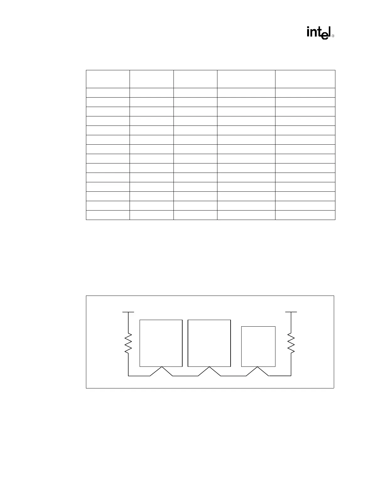
5.3.1 Asynchronous GTL+ Signals Driven by the Processor
Follow the topology shown in Figure 5-4 when routing FERR#, IERR#, PROCHOT# and
THERMTRIP#. Note that FERR# is the only signal in this group that connects the processors to the
ICH3-S. IERR#, PROCHOT# and THERMTRIP# connect to other motherboard logic (such as the
Baseboard Management Controller) and may need voltage translation logic, depending on the
motherboard receiver logic devices used. Do not route a stub when routing to the processors.
NOTES:
1. Trace Z
0
= 50 Ω.
2. Trace spacing = 10 mil.
SM_DAT SMBUS (3.3 V) I/O Processor/Controller Processor/Controller
SM_EP_A[2:0] SMBUS (3.3 V) I Pull-up / Pull-down Processor
SM_TS_A[1:0] SMBUS (3.3 V) I Pull-up / Pull-down Processor
SM_WP SMBUS (3.3 V) I External Logic Processor
SMI# Async GTL+ I ICH3-S Processor
STPCLK# Async GTL+ I ICH3-S Processor
THERMTRIP# Async GTL+ O Processor External Logic
VCCA Power I Pull-up / Pull-down Processor
VCCIOPLL Power I Pull-up / Pull-down Processor
VCCSENSE Other O Processor Voltage Regulator
VID[4:0] Other O Processor Voltage Regulator
GTLREF Power I Pull-up / Pull-down Processor
VSSA Power I Pull-up / Pull-down Processor
VSSSENSE Other O Processor Voltage Regulator
Table 5-6. Asynchronous GTL+ and Miscellaneous Signals (Sheet 2 of 2)
Signal Name Type
Processor
I/O Type
Driven By Received By
Figure 5-4. Topology for Asynchronous GTL+ Signals Driven by the Processor
Intel
®
ICH3-S
or other logic
Processor 0 Processor 1
VCC_CPU
0.1" – 3.0"
0.1" – 10.0" 0.1" – 10.0" 0.1" – 10.0"
VCC_CPU
56 Ω ± 5% 56 Ω ± 5%