EMI and Mechanical Design Considerations
152 Design Guide
Differential clocking can also reduce the amount of noise coupled to other traces, which improves
signal quality and reduces EMI. I/O signals are particularly important because they often leave the
system chassis (serial and parallel ports, keyboards, mouse, etc.), and radiate noise that has been
induced onto them. A single-ended clock's return path is usually a reference plane, which is shared
by other signals/traces. When noise is created on a single-ended clock, the noise will appear on the
reference plane and may be coupled to I/O traces. A differential clock's return path is the clock-bar
signal/trace, which is more isolated than the reference plane and minimizes potential I/O trace
coupling.
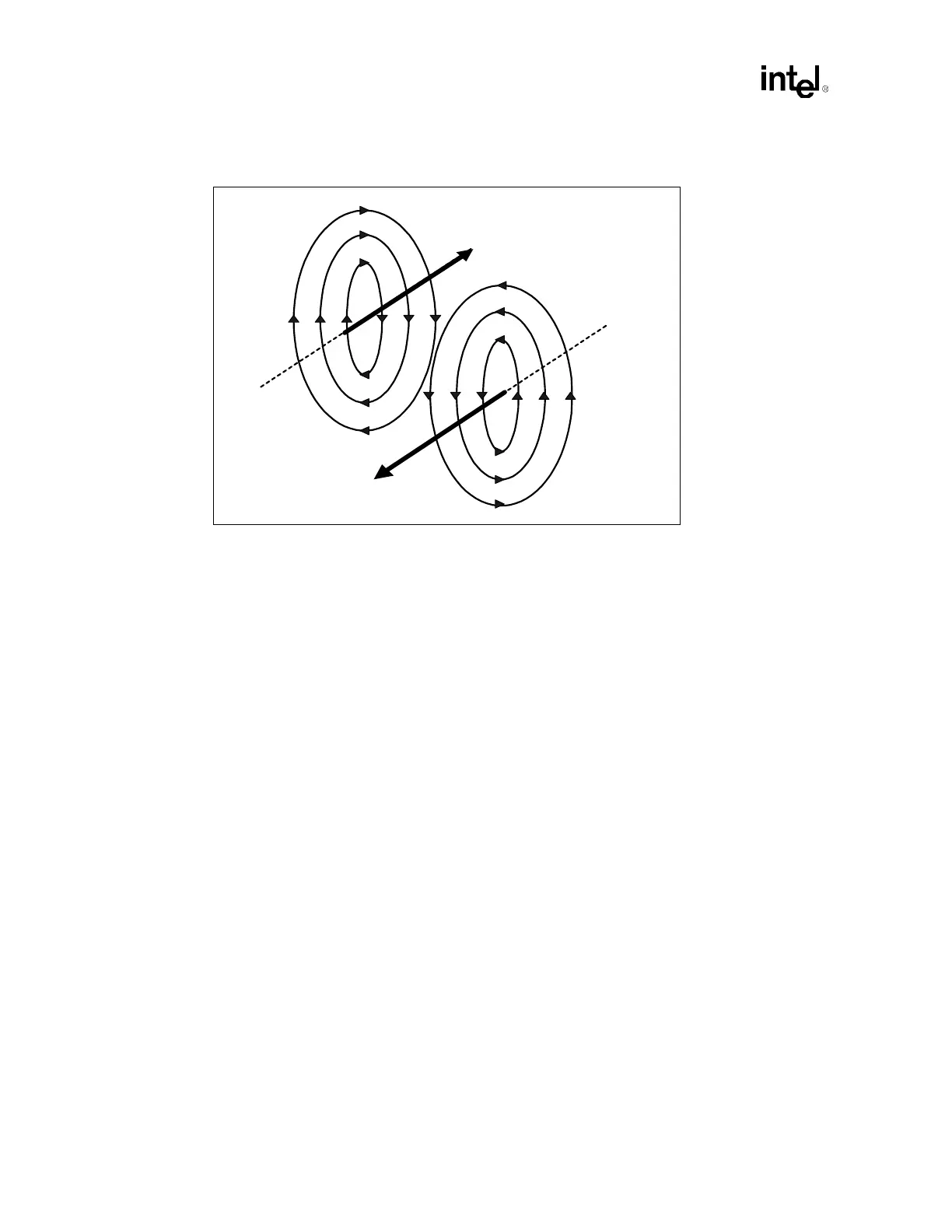
For best results, the trace lengths and routing of the clock lines must be closely matched, and
spacing between the two traces should be kept as small as possible. This will minimize loop area
and maximize H-field cancellation. In addition, the real and parasitic terminations of each signal of
a differential pair should be the same. Also, the skew between the signal level transitions on the
two lines must be small compared to the rise time of the level transitions.
Placing ground traces on the outside of the differential pair may further reduce emissions.
Intermediate vias to ground may be needed to reduce the opportunity for re-radiation from the
ground traces themselves. Distance between vias should be less than ¼ of a wavelength of the fifth
harmonic of the processor core frequency.
11.2.3 PCI Bus Clock Control
Experimental data has indicated a reduction in EMI may be possible by disabling the clocks to
unused (and therefore unterminated) PCI slots. CK408B, the clock chip that has been specified and
designed for this platform, supports individual control of the various PCI clocks. Designers have
the option to enable or disable individual PCI clocks depending upon their specific system
configuration requirements. Refer to the CK408B Clock Synthesizer Design Guidelines for details
on how to configure the PCI clocks.
Figure 11-3. Cancellation of H-fields Through Inverse Currents
CLK - clock trace
CLK' - clock bar
trace
H-field
caused by
Iclk
Iclk
Iclk'
H-field
caused by
Iclk'