Design Guide 113
Intel
®
82870P2 (P64H2)
8.2.7.7 Pull-Ups/Pull-Downs in Three or More Slot Serial Mode
All PCI signals should follow the PCI Local Bus Specification, Revision 2.2 pull-up requirements
whether they are muxed or not. Any unused input signals should be pulled to 3.3 V through an
8.2
kΩ ± 5% resistor to keep them from floating.
Table 8-13. Shift Register Input Data
Bit Byte 0 Byte 1 Byte 2 Byte 3
0 Slot 1 switch (0 = closed) Slot 1 fault# (0 = fault) Slot 1 present bit 2 Slot 1 present bit 1
1 Slot 2 switch Slot 2 fault# Slot 2 present bit 2 Slot 2 present bit 1
2 Slot 3 switch Slot 3 fault# Slot 3 present bit 2 Slot 3 present bit 1
3 Slot 4 switch Slot 4 fault# Slot 4 present bit 2 Slot 4 present bit 1
4 Slot 5 switch Slot 5 fault# Slot 5 present bit 2 Slot 5 present bit 1
5 Slot 6 switch Slot 6 fault# Slot 6 present bit 2 Slot 6 present bit 1
6 Stutter (not used) Stutter (not used) Stutter (not used) Stutter (not used)
7 Stutter (not used) Stutter (not used) Stutter (not used) Stutter (not used)
Bit Byte 4 Byte 5 Byte 6 Byte 7
0 Slot 1 M66EN Slot 1 PCIXCAP1 Slot 1 PCIXCAP2 User Defined
1 Slot 2 M66EN Slot 2 PCIXCAP1 Slot 2 PCIXCAP2 User Defined
2 Slot 3 M66EN Slot 3 PCIXCAP1 Slot 3 PCIXCAP2 User Defined
3 Slot 4 M66EN Slot 4 PCIXCAP1 Slot 4 PCIXCAP2 User Defined
4 Slot 5 M66EN Slot 5 PCIXCAP1 Slot 5 PCIXCAP2 User Defined
5 Slot 6 M66EN Slot 6 PCIXCAP1 Slot 6 PCIXCAP2 User Defined
6 Stutter (not used) Stutter (not used) Stutter (not used) Stutter (not used)
7 Stutter (not used) Stutter (not used) Stutter (not used) Stutter (not used)
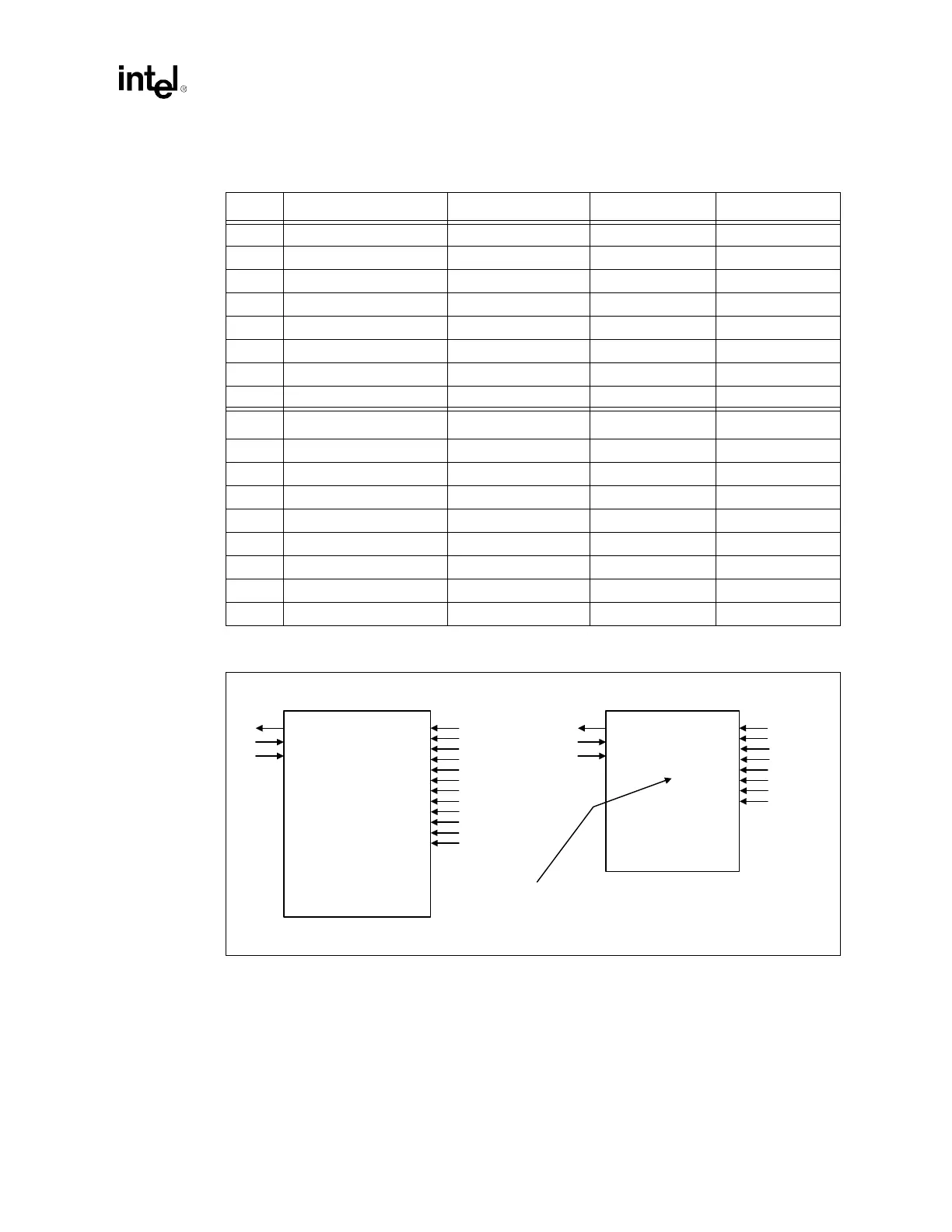
Figure 8-15. Four Slot Stutter Logic Implementation Example
Slot 1 Switch
Slot 2 Switch
Slot 3 Switch
Slot 4 Switch
Slot5 Switch
Slot 6 Switch
Slot 1 Fault
Slot 2 Fault
Slot 4 Fault
Slot 5 Fault
Slot 6 Fault
Parallel Load
Incorrect Implementation Correct Implementation
Serialization
Logic
Serialized
Data
Serial Clock In
Slot 3 Fault
Connected
Connected
Connected
Connected
Grounded
Grounded
Connected
Connected
Connected
Connected
Grounded
Grounded
Serialization
Logic
Parallel Load
Serialized
Data
Serial Clock In
Slot 1 Switch
Slot 2 Switch
Slot 3 Switch
Slot 4 Switch
Connected
Connected
Connected
Connected
Slot 1 Fault
Slot 2 Fault
Slot 4 Fault
Slot 3 Fault
Connected
Connected
Connected
Connected
Notice that Slot 5
and Slot 6 positions
have been skipped.