Hub Interface
86 Design Guide
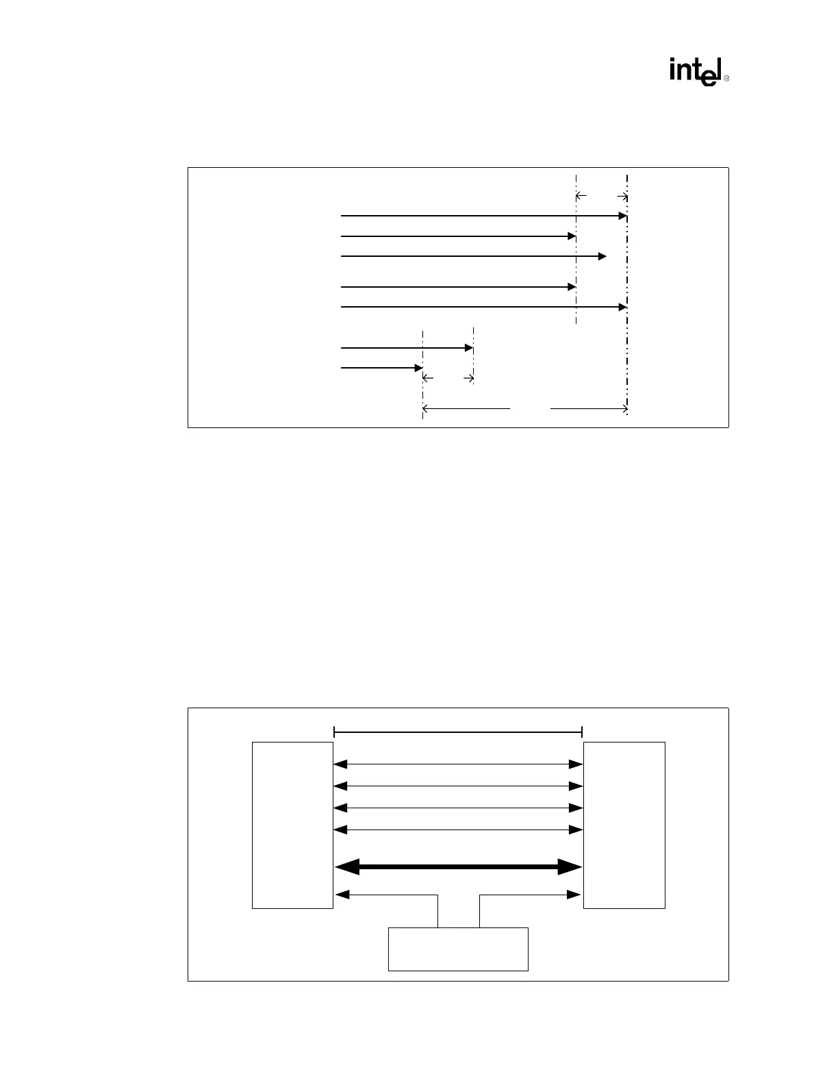
NOTES:
1. All signal lines with arrows depict the total length of the signal including the mother board trace length, MCH
package trace length, and Hub Interface 2.0 device trace length.
2. PUSTRBF and PUSTRBS length matching is the same as for PSTRBF and PSTRBS.
3. This figure is only an example for an implementation with the device on the motherboard. For an
implementation with the hub interface device on a riser card, simply replace both instances of 0.25”
with 0.125”.
4. In the example above, HI[x], HI[y], and HI[z] represent Hub Interface data signals. The other six data signals
in the group must also be matched within 0.25”. The associated strobe pair must be within 1.0” of the longest
data signal.
Hub Interface 2.0 has a minimum trace length requirement of 3 inches, and a maximum trace
length requirement of 20 inches for a device on the motherboard implementation for all hub
interface signals (using an internal routing layer on the recommended stackup). However, for a
device on an adapter card plugged in a hub interface 2.0 connector, the maximum motherboard
trace length is 14 inches. For a riser card topology, the maximum trace length would reduce to
3 inches to (11-Y) inches, where Y is the riser card trace length. The riser must be built to not
exceed the maximum trace length with the motherboard routed length.
Figure 7-2. Hub Interface 2.0 Length matching
HI[x]
HI[z]
HI[y]
PSTRBF
PSTRBS
- OR -
PSTRBF
PSTRBS
1.0 "
0.25"
0.25"
Figure 7-3. Hub Interface 2.0 Routing Guidelines for Device Down Solutions
MCH
Intel
®
P64H2
CK408B
CLK66 CLK66
PSTRBF
PSTRBS
PUSTRBF
PUSTRBS
HI_[21:0]
3" - 20"