Platform Power Delivery Guidelines
174 Design Guide
In addition, high-frequency decoupling may be required for signal integrity. System boards
designed using striplines with VCC_CPU and VSS references should not require high-frequency
decoupling beyond the recommendations listed in Table 12-5. For systems using microstrip
configurations, a return path discontinuity will exist between the processor and the baseboard due
to the baseboard traces having only one reference plane. These systems should distribute
decoupling capacitors, as shown in Figure 12-11 and described as follows:
• 4 minimum, 6 preferred 1 µF capacitors with 0805 packages distributed evenly over the data
lines.
• 3 minimum, 4 preferred 0.1 µF capacitors with 0805 packages distributed evenly over the
address and control lines.
Location of High-Frequency Decoupling
Place high-frequency decoupling as close to the power pins of the processor as physically possible.
Use both sides of the board if necessary for placing components to achieve the optimum proximity
to the power pins. This is vital because the inductance of the board's metal plane layers could
cancel the usefulness of these low inductance components.
Shorten the path from the capacitor pads to the pins that it is decoupling. If possible, place the vias
connecting to the planes within the pad of the capacitor. If this is not possible, keep the traces as
short and wide as is feasible. Possibly one or both ends of the capacitor can be connected directly to
the pins of the processor without the use of a via. Figure 12-12 illustrates these concepts.
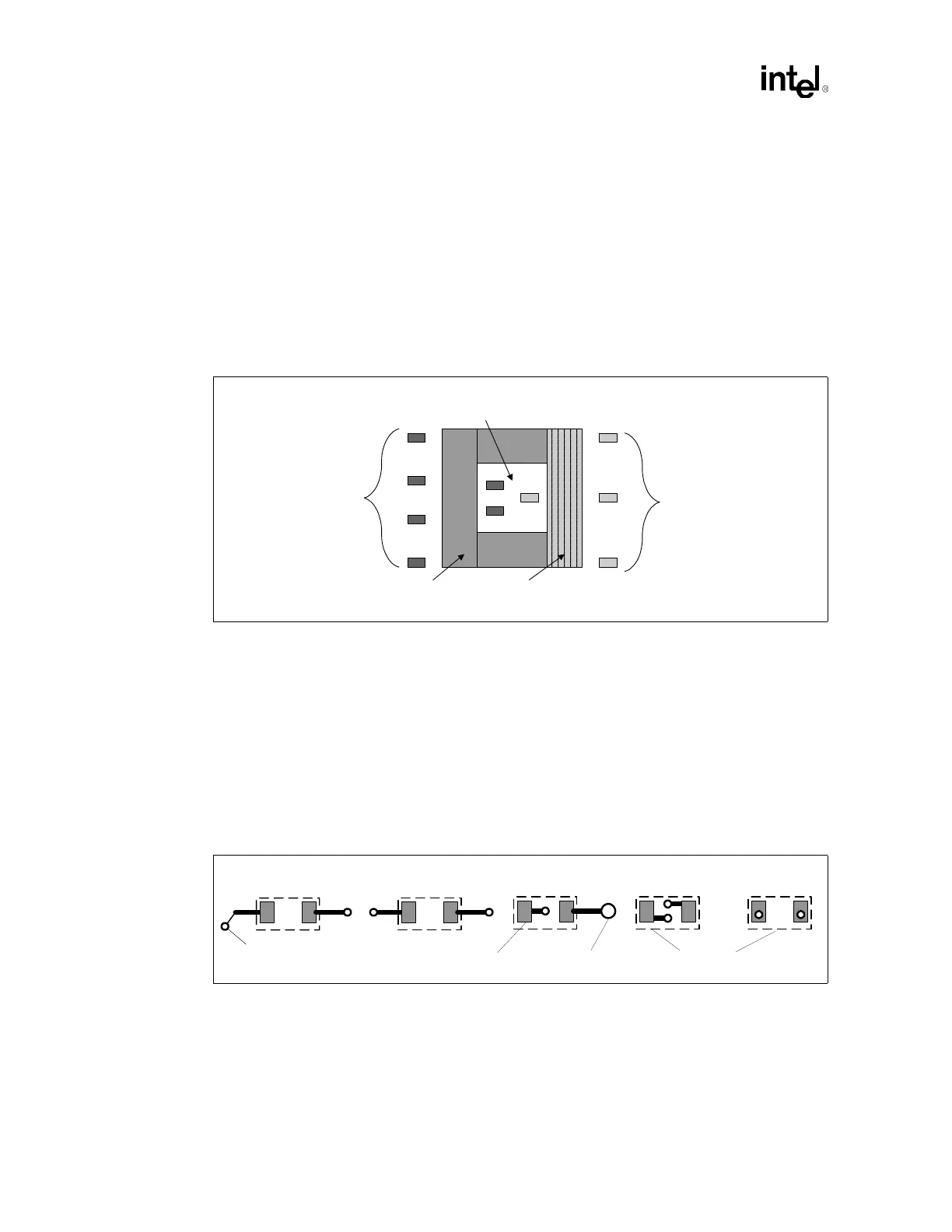
Figure 12-11. Decoupling Example for a Microstrip Baseboard Design
3-4 0.1 uF with 0805
body over the address
and control signals and
as close to the processor
package as possible.
4-6 0.1 uF with 0805
body over the data
signals and as close
to the processor
package as possible.
Data Pins
Address and
Control Pins
Cavity Under
Processor
Figure 12-12. 1206 Capacitor Pad and Via Layouts
Bad
Vias
Very Good
Pad
Capacitors
Good
Pin
Less Bad
Very Good