Design Guide 69
Memory Interface Routing Guidelines
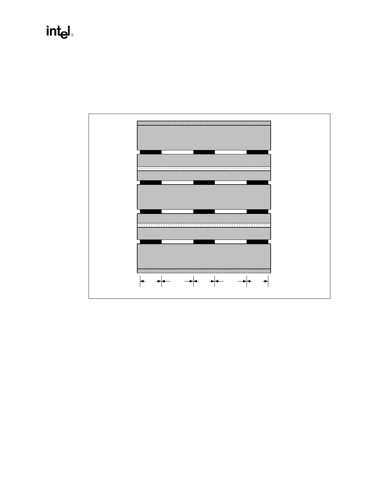
The DDR interface requires a nominal impedance (Zo) of 50 Ω ± 10%. Using the recommended
stackup, all routing layers yield 50 Ω nominal impedance when using 5 mil wide traces. Route all
DDR signals 5/15 (5 mils wide with 15 mil spacing) as shown in Figure 6-3 with the exception of
CKE, CMDCLK[3:0], and CMDCLK[3:0]#. For CMDCLK routing rules, refer to Section 6.3 and
Figure 6-8. For CKE routing rules, refer to Section 6.6 and Figure 6-3. Route layers 4 and 5
orthogonal to each other to minimize crosstalk.
NOTES:
1. Traces on layers 4 and 5 must be routed orthogonally to each other to minimize the effects of crosstalk.
2. Source Synch., Source Clocked, and CS# are routed 5/15.
3. CKE is routed 7.5/15.
Figure 6-3. Trace Width and Spacing for All DDR Signals Except CMDCLK/CMDCLK#
Core 5.2 mil
Dielectric 9.6 mil
2.1 mil (1 oz + plating)
Power
Dielectric
Power
Dielectric
Ground
Main Core
Dielectric
Core
Ground
Dielectric
Core
1.4 mil (1 oz)
2.1 mil (1 oz + plating)
Core 5.2 mil
Dielectric 4.3 mil
Core 14.0 mil
Dielectric 9.6 mil
Dielectric 4.3 mil
Layer 1
Layer 2
Layer 3
Layer 4
Layer 5
Layer 6
Layer 7
Layer 8
Signal Signal Signal
SignalSignal
SignalSignal
SignalSignal
Trace
Width
1.4 mil (1 oz)
1.4 mil (1 oz)
Signal
Signal 1.4 mil (1 oz)
1.4 mil (1 oz)
1.4 mil (1 oz)
Signal
Trace
Spacing
Trace
Spacing
Trace
Width
Trace
Width