Design Guide 127
I/O Controller Hub
Both the SMBus Host Controller and the SMBus Slave Interface obey the SMBus 1.1 protocol, so
the two interfaces can be externally wire-OR'd together to allow an external management ASIC
(such as 82550) to access targets on the SMBus as well as the ICH3-S Slave interface.
Additionally, the ICH3-S supports slave functionality, including the Host Notify protocol, on the
SMLink pins. This is done by connecting SMLink0 to SMBCLK and SMLink1 to SMBDATA.
Intel does not support external access of the ICH3-S's Integrated LAN Controller via the SMLink
interface. In addition, Intel does not support access of the ICH3-S's SMBus Slave Interface by the
ICH3-S's SMBus Host Controller. Refer to the Intel
®
82801CA I/O Controller Hub 3 (ICH3-S)
Datasheet for full functionality descriptions of the SMLink and SMBus interface.
9.5.1 SMBus Design Considerations
Designing an SMBus using the ICH3-S is based on the power supply source for the SMBus
microcontrollers. For the platform, all devices are powered by VCC_3.3; therefore, the preferred
design choice is the unified VCC_3.3 architecture.
9.5.2 General Design Note
The pull-up resistor size for the SMBus data and clock signals is dependent on the number of
devices present on the bus. A typical value is 8.2 kΩ
± 5%. This should prevent the SMBus signals
from floating, which could cause leakage in the ICH3-S and other devices.
9.5.3 The Unified VCC_CORE Architecture
In the unified VCC_CORE architecture, all SMBus devices are powered by the VCC_3.3 supply.
This architecture in Figure 9-8 allows none of the devices to operate in STR, minimizing the load
on 3.3 V SUSPEND.
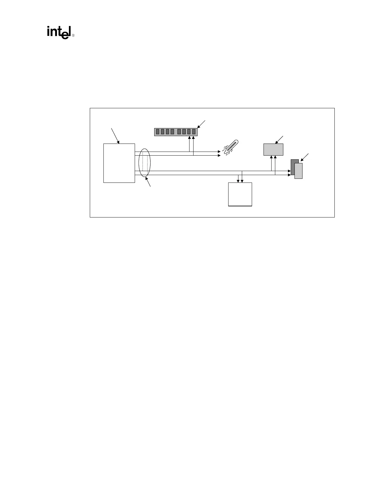
Figure 9-7. Intel
®
ICH3-S SMBus / SMLink Interface
Intel
®
ICH3-S
Host Controller and
Slave Interface
SMBus
SMBCLK
SPD Data
Temperature on
Thermal Sensor
Network
Interface Card
on PCI
Microcontroller
Motherboard
LAN
Controller
Wire OR
(optional)
SMLink0
SMLink1
SMLink
SMBDATA